


Whole garment knitting-enabled direct current triboelectric nanogenerators
 0
0 
Abstract
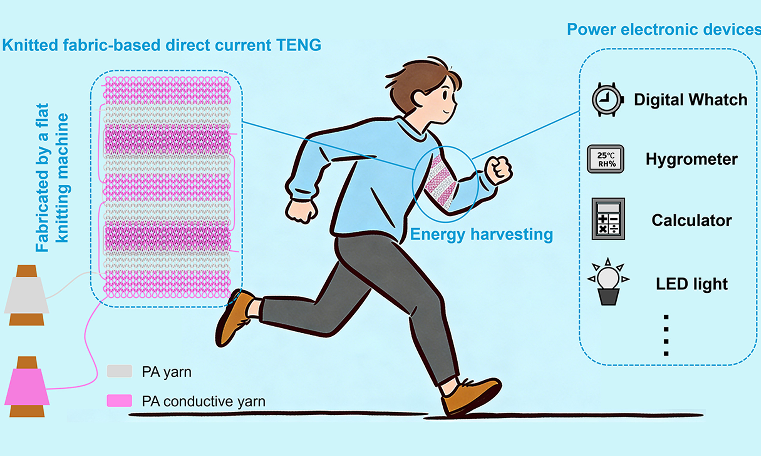
Wearable electronics require compact, reliable, and sustainable power sources. Fabric-based triboelectric nanogenerators (TENGs) offer a promising solution by combining energy harvesting with the inherent softness and breathability of textiles. However, conventional functionalization methods, such as surface coatings or multilayer structures, inevitably diminish these essential properties. To address this issue, we developed a knitted fabric-based direct current triboelectric nanogenerator (KF DC-TENG) using whole-garment knitting technology and the air breakdown effect. This design allows direct application without complex post-processing and eliminates the need for external rectification. A single unit of KF DC-TENG (8 × 2.5 cm2), after structural optimization, is capable of lighting 744 series-connected Light Emitting Diodes (LEDs) when manually rubbed against polytetrafluoroethylene (PTFE) fabric. Integration with a low-cost power management circuit (PMC, ~1.5 CNY) further enhances the output power by 290 times. As a result, 17 s of friction can power an electronic watch for up to 8 min. Moreover, continuous sliding can sustain a
Keywords
INTRODUCTION
In the era of rapid technological advancement, the advent of the Internet of Things (IoT) has significantly enhanced daily life by enabling seamless communication between devices[1,2]. This interconnectivity has not only transformed the way we interact with technology but also revolutionized the field of wearable electronics[3,4]. Traditionally used for clothing and warmth, fabrics have now evolved into intelligent materials capable of real-time monitoring of human movement and health metrics through embedded sensors[5,6]. However, the development of wearable devices remains limited by power supply constraints. Conventional batteries, with their finite energy density, often require a trade-off between size and capacity, thus restricting the potential of wearable technology[7,8]. Triboelectric nanogenerators (TENGs) have emerged as a promising alternative for sustainable power generation, offering efficient energy conversion within a compact structure[9]. Fabric-based TENGs, in particular, have garnered attention due to their inherent softness and breathability, enabling seamless integration into clothing while maintaining wearer comfort. They can effectively harvest mechanical energy from daily activities and provide a continuous power supply for embedded sensors in wearable systems[10]. However, conventional TENGs typically generate alternating current (AC)[11,12], which is incompatible with most wearable electronics that rely on direct current (DC). The conversion from AC to DC introduces additional energy loss and system complexity. Therefore, direct current TENGs (DC-TENGs), which eliminate the need for rectification, represent a more efficient strategy[13-15].
Existing DC-TENGs can be classified into three main mechanisms: air breakdown[16-19], the tribovoltaic effect[20-23], and mechanical rectification[24-27]. Air breakdown-based TENGs are particularly notable due to their relatively simple structure and superior output performance. This makes them highly suitable for applications requiring high power output and stability. Furthermore, the Van de Graaff generator’s design inspired air breakdown DC-TENGs[28]. Yang et al. developed the first belt-type DC-TENG that transfers charges via moving belts[29]. Unlike the Van de Graaff unit for high-voltage applications, this DC-TENG employs self-generated high voltage to trigger air breakdown, thereby spontaneously equalizing interfacial potentials and delivering direct current output. Liu et al. further simplified the design by suspending electrodes to establish air-breakdown gaps[30]. This approach eliminates belt-mediated charge transfer, directly harvesting frictional charges between two materials while consolidating charge-transfer and charge-collection functions using the same conductive material. Similarly, Chen et al. used an acrylic board with an uneven surface as the substrate and strategically placed two sets of conductive yarns in the fabric at the highest and lowest positions of the acrylic board as the frictional electrode and electrostatic breakdown electrode[31], respectively. This innovative design enabled the development of a fabric-based DC-TENG utilizing air breakdown. However, despite these significant advancements, fabric-based DC-TENGs through air breakdown still face several challenges. These include limited practical applicability and complex post-processing procedures. For example, polymer coatings on yarns or fabrics and additional sewing steps are often required, making the fabrication process cumbersome and less practical for large-scale applications[4,10]. Therefore, simplifying the fabrication process and enhancing wearability remain critical for advancing fabric-based DC-TENGs toward real-world wearable applications.
In addition, TENGs typically exhibit high voltage, low current, and extremely high internal impedance, leading to low energy utilization efficiency when directly driving low-impedance electronic devices. To address this challenge, effective power management systems are required to improve energy utilization in practical applications[32-35]. The earliest power management for TENGs can be traced back to 2013, when Cheng et al. utilized the motion of TENGs to delay energy release[36], thereby obtaining high-peak-pulse currents. This type of power management is a kind of mechanical rectification that needs to be used in combination with the motion of TENGs and switches. In 2020, Harmon et al. developed a self-powered power management system (PMS)[37]. Compared with the previous methods, the PMS does not rely on the specific motion patterns of the TENG to control the switch[38], nor does it require any special structural design[39,40]; it only requires charging the front-stage capacitor to complete the switch-off operation. Cheng et al. developed two kinds of fabric-based DC-TENGs that utilize air breakdown by coating the fabric with conductive silver paste as electrodes[41,42]. Among them, Ref.[42] fabricated an energy management module (EMM), which, after processing through the EMM, is capable of lighting up four 30 W commercial light bulbs, demonstrating remarkable output performance and highlighting the significant potential of power management circuits in enhancing energy output.
In this study, we present a knitted fabric-based DC-TENG (KF DC-TENG) that utilizes air breakdown and exploits the unique properties of knitted structures. Silver-coated polyamide (PA) yarns serve as electrodes, while insulating PA yarns are introduced in the insulating region to prevent inter-electrode conduction. The electrode gap can be conveniently tuned by adjusting the number of conductive knitting yarns. Whole-garment knitting technology is employed to create a stable three-dimensional air-breakdown gap in a single step, eliminating the need for complex post-processing. Additionally, the structural asymmetry between interlock and plain stitches enables dual-sided DC output, improving mechanical energy utilization efficiency. To address the low energy utilization issue of TENGs, a low-cost power management circuit (PMC) costing only ~1.5 CNY is developed, which boosts the energy output by nearly 290 times and enables stable power supply for electronic watches and Light Emitting Diodes (LEDs). The KF DC-TENG exhibits excellent softness and breathability and is compatible with standard knitting computer aided design (CAD) programs, facilitating scalable industrial production. After systematic optimization, a single unit (total geometric area of 8 × 2.5 cm2) can light 744 series-connected LEDs when rubbed against polytetrafluoroethylene (PTFE) fabric, while four units interfaced with fluorinated ethylene propylene (FEP) film can light 1,392 LEDs. Notably, the device maintains stable output even after 14,000 friction cycles, demonstrating excellent durability. With the PMC, the KF DC-TENG delivers a peak pulse current of 20 mA under no-load conditions, charges a 100 μF capacitor to 20 V within 1 min, and can power an electronic watch for 8 minutes after only 17 seconds of charging. These results demonstrate the facile fabrication and high output performance of the KF DC-TENG, revealing its strong potential for wearable energy-harvesting applications.
EXPERIMENTAL
Materials
The silver-coated PA yarns [100 Denier (D)] were purchased from Qingdao Tianyin Textile Technology Co., Ltd., Qingdao, Shandong, China. The PA fibers (75 D) were obtained from Dongguan Coco Textile Materials Co., Ltd., Dongguan, Guangdong, China. The FEP film (80 μm) was sourced from Taizhou Chenguang Plastic Industry Co., Ltd., Taizhou, Jiangsu, China. The acrylic plate was bought from Dianjin Plastics Co., Ltd., Wenzhou, Zhejiang, China.
Fabrication of the KF DC-TENG
The KF DC-TENG was fabricated using a double-bed computerized flat knitting machine. The optimized fabric structure was produced with four yarn feeders. The first yarn feeder was used to knit the waste yarn for smooth fabric formation. The other three feeders were used for the main part of the fabric. The third yarn feeder used 600D PA yarn to knit the insulating plain stitch part of the fabric. The fourth and fifth yarn feeders used 600D and 400D silver-coated PA yarns, respectively. The fourth yarn feeder knitted the triboelectric electrode in an interlock structure, while the fifth yarn feeder knitted the breakdown electrode in a plain stitch structure. For more detailed knitting processes, see Supplementary Notes 1 and 2.
Device characterizations
The KF DC-TENG was manufactured using a double-bed computerized flat knitting machine (KSC132A-14G, Jiangsu Jinlong Technology Co., Ltd., Changshu, Jiangsu, China). The thicknesses of the KF DC-TENGs were measured using a digital fabric thickness tester (YG141LA, Ningbo Textile Instrument Factory, Haishu District, Ningbo, Zhejiang, China). The fabric air permeability was tested using a Fully Automatic Air Permeability Instrument (YG461E-III, Ningbo Textile Instrument Factory, Haishu District, Ningbo, Zhejiang, China). The acrylic plate was cut using a laser cutting machine (YQ-E6040, Suzhou Yi Guangguang Electric Technology Co., Ltd., Suzhou, Jiangsu, China). The periodic contact-sliding movements were driven by a commercial linear mechanical motor (LinMot E1100, NTI AG, Spreitenbach, Switzerland). The short-circuit current and transferred charge of the KF DC-TENG were measured using an electrometer (Keithley 6514, Keithley Instruments, Inc., Cleveland, Ohio, the United States), while the open-circuit voltage was measured using an electrometer with a high-voltage probe (HVP-40, 1/1000, 1000 MΩ, Tektronix, Inc., Beaverton, Oregon, United States). The resistances of the friction electrode, breakdown electrode, and silver-coated PA yarn were measured using a digital multimeter (VICTOR, model VC980, Shenzhen Yisheng Shengli Technology Co., Ltd., Futian District, Shenzhen, Guangdong, China).
RESULTS AND DISCUSSION
The human understanding of electricity dates back to observations of lightning, and modern technologies have enabled its controlled use to improve daily life. Here, we harness electrostatic breakdown generated by fabric friction - analogous to “lightning” within textiles - to power electronic devices. However, constructing a three-dimensional breakdown gap using inherently two-dimensional fabrics remains a significant challenge in fabric-based air breakdown DC-TENGs. The structural characteristics of knitted fabrics offer an effective solution to this challenge. Fabrics knitted on a double needle bed are typically thicker than those from a single needle bed, and this thickness difference can provide the gap necessary for air breakdown, enabling efficient energy conversion in DC-TENGs. Accordingly, we employed interlock stitch (double-needle-bed) as the friction electrode and plain stitch (single-needle-bed) as the breakdown electrode [Figure 1A]. To prevent electrical conduction between the two electrodes, they were knitted with separate sets of conductive yarns, with an insulating PA plain stitch section inserted between them. For a more in-depth explanation of the design principle and methods to address the potential cross-conduction issue, see Supplementary Note 1. As each electrode is formed from a continuous set of yarns, the friction and breakdown electrodes are inherently connected within their respective circuits [Figure 1B]. The detailed machine diagram and knitting process are provided in Supplementary Figure 1 and Supplementary Note 2. All yarns used are commercially available. Silver-coated PA yarns exhibit excellent electrical conductivity: six 10 cm strands of 100D silver-coated PA show a resistance of only 9 Ω, which decreases to 5 Ω and 2 Ω after being knitted into the friction and breakdown electrodes, respectively [Supplementary Figure 2]. Owing to the interlocking loop structure of weft-knitted fabrics, the inherent gaps between loops provide high breathability. Air permeability testing revealed an average value of ~1,500 mm/s at a pressure difference of 100 Pa for a 20 cm2 test area [Supplementary Figure 3]. Loop size, and thus breathability, can be tuned by adjusting the needle lowering depth during knitting, with greater lowering depths resulting in higher air permeability [Supplementary Note 3].
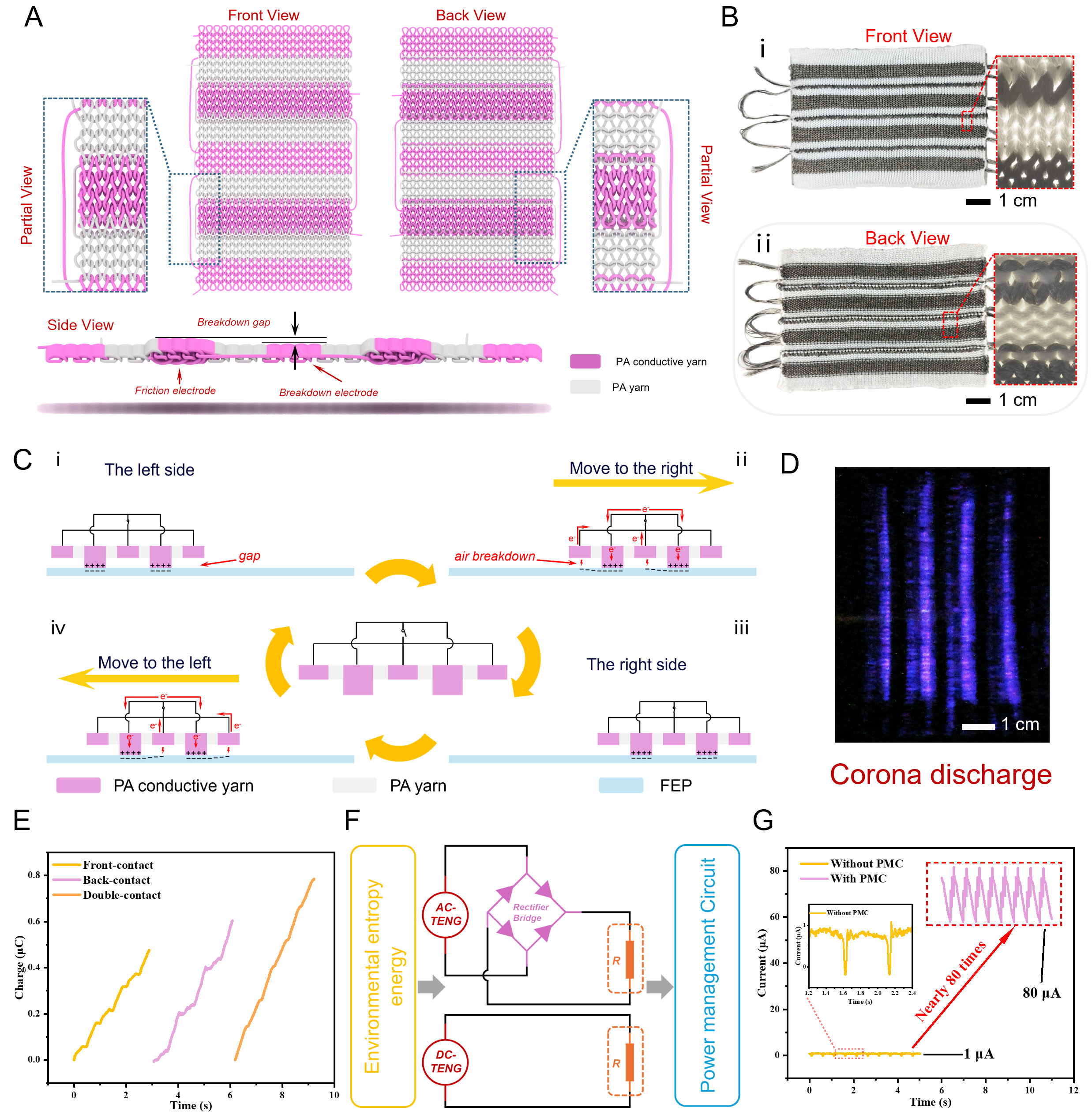
Figure 1. Structure and working mechanism of the KF DC-TENG. (A) Simulation diagram of KF DC-TENG, (B) actual photograph of KF DC-TENG, (C) motion cycle diagram of KF DC-TENG, (D) corona discharge, (E) charge output of single-contact and double-contact, (F) energy harvesting and optimization, (G) output comparison of TENG with and without power management circuit. TENG: Triboelectric nanogenerator; KF DC-TENG: knitted fabric-based direct current TENG; PMC: power management circuit; AC: alternating current; PA: polyamide.
The working principle of the KF DC-TENG under contact sliding is shown in Figure 1C. When the fabric contacts FEP (stage ⅰ), the breakdown electrode, supported by the friction electrode, forms a small air gap. Due to the different electronegativities of various materials, FEP, owing to its strong electronegativity, can capture electrons from the surface of the silver-coated PA. As the KF DC-TENG slides to the right side (stage ii), a high-density charge layer forms on the FEP surface after friction. When the breakdown electrode passes over this charged surface, a strong electric field develops between the FEP and the electrode. Once the electric field reaches a critical strength, charges are ejected from the FEP surface, ionizing the air to form a conductive channel. These charges are collected by the breakdown electrode and returned to the friction electrode via the external circuit. Meanwhile, the friction electrode continuously transfers electrons to the FEP surface through the triboelectric effect during the sustained contact and friction with FEP. When the KF DC-TENG slides to the left (stages iii and iv), the same process occurs. To demonstrate that air breakdown indeed occurs during fabric sliding, time-lapse photography was employed to capture the glow discharge in a completely darkened test environment, as shown in Figure 1D. Due to the unevenness of the fabric, air breakdown also occurs near the friction electrode. Additionally, the interlock stitch, which forms raised areas on both sides of the fabric, enables both sides of the KF DC-TENG to generate output through friction [Supplementary Figure 4]. When both sides are rubbed simultaneously, the charge generated by three cycles of double contact is higher than that generated by single contact [Figure 1E]. Simultaneous sliding of both sides allows both the front and back surfaces of the friction electrode to contact FEP, thereby facilitating charge transfer. Therefore, air breakdown occurs on both sides of the breakdown electrode, which leads to a higher output compared to single-sided contact. Details of the testing method, along with the measured current and voltage, are presented in Supplementary Figure 5. Notably, the DC-TENG can power electronic components without the need for rectification by a rectifier bridge [Figure 1F]. However, the inherently high impedance of the TENG limits its ability to achieve maximum output power under low load conditions. To address this, this study presents a detailed investigation of a PMC, which enhances the current output by nearly 80 times compared with the original fabric [Figure 1G].
To evaluate the fabric’s output under different conditions, we employed the testing platform shown in Figure 2A, which allowed precise control of parameters such as speed and displacement. The acceleration, velocity, and displacement of the linear motor were set to 10 m/s2, 0.1 m/s, and 50 mm, respectively, while the relative humidity was maintained at 40% relative humidity (RH). Unless otherwise specified, these parameters were kept constant in all subsequent tests. To determine the optimal output structure of the KF DC-TENG, we systematically examined the influence of six factors: the number of knitted courses of the insulating plain stitch (A), the number of knitted courses of the breakdown electrode (B), the number of knitted courses of the friction electrode (C), the number of knitted wales of the fabric structure (D), the minimum number of knitting cycles (E), and the breakdown gap (F) on its output performance [Figure 2B]. To ensure a consistent number of breakdown electrodes during motion cycles, an additional breakdown electrode was incorporated into the structure. Unless otherwise specified, all samples consisted of two friction electrodes and three breakdown electrodes, fabricated using 600D silver-coated PA yarns and PA yarns. As shown in Figure 2C and D, the output decreased as A increased. Based on the fabric’s motion process [Supplementary Figure 6 and Supplementary Note 4], a larger A reduced the effective charge-collection area of the electrodes, thereby lowering the output. Notably, when A = 3, the output does not reach its maximum, because the breakdown and friction electrodes are positioned too closely. In addition, fuzz generated on the conductive yarn surface during knitting can cause short circuits between electrodes, further reducing the output. This highlights the importance of controlling the electrode spacing during knitting to prevent short circuits. As shown in Figure 2E, the current does not return to zero during fabric motion, which is attributed to surface irregularities that induce charge accumulation at sharp points on the breakdown electrodes. Consequently, multiple electrostatic breakdown events occur simultaneously during sliding, and their superposition prevents the current from returning to zero. As the value of B increases, the breakdown electrodes gain more irregular sharp tips. Although these tips do not enlarge the effective charge-collection area [Supplementary Figure 7], they form strong local electric fields with the FEP film, enabling more breakdown events to occur during fabric sliding and thereby increasing the output [Figure 2F]. As shown in Figure 2G and H, the output decreased as the value of C increased. This reduction is attributed to decreased contact pressure on the friction electrode. Under a constant normal force, increasing the electrode area reduces interfacial contact with the FEP film, thereby limiting charge transfer. Furthermore, reduced pressure enlarges interfacial gaps, promoting air breakdown and decreasing the surface charge density of FEP, which is consistent with the corona discharge observed in Figure 1D. As shown in Figure 2I and J, the output increases as D increases. As the friction electrode area expands, the sliding contact area on the FEP surface also increases, thereby enlarging the effective air breakdown region. Furthermore, as shown in Figure 2K and L, an increase in the knitting cycle number E resulted in an increase in the output. Compared with E = 1, E = 2 introduces an additional central electrode, resulting in higher output. Furthermore, a larger E corresponds to the participation of more breakdown electrodes, leading to enhanced output.
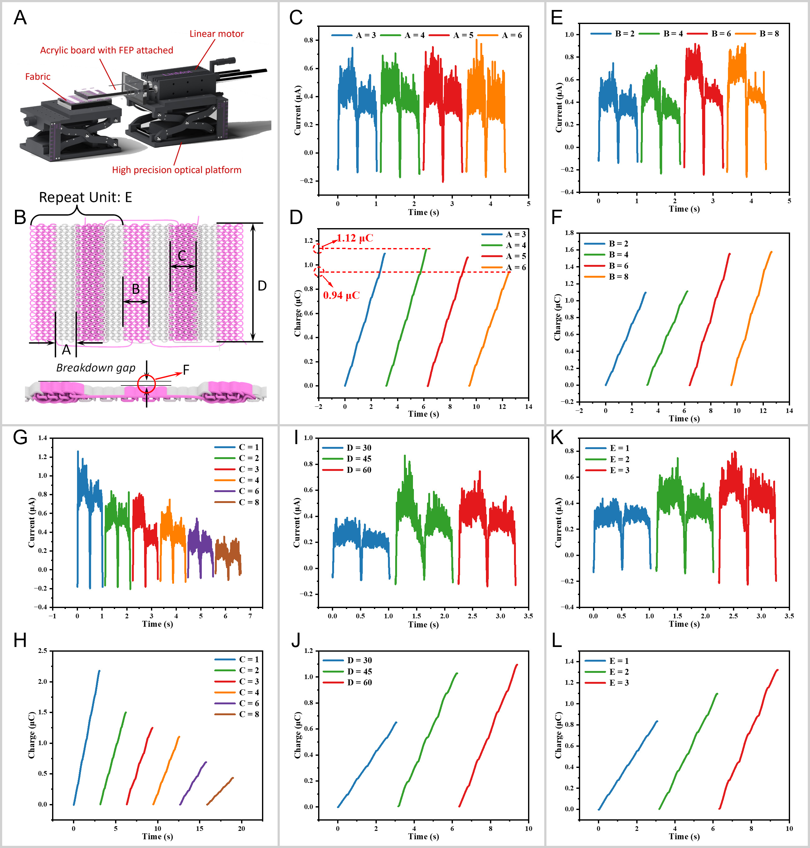
Figure 2. The Influence of Fabric Structure on the Output Performance of KF DC-TENG. (A) Test platform, (B) fabric structure, (C) current and (D) charge transfer of KF DC-TENG under different insulating plain knit courses, (E) current and (F) charge transfer of KF DC-TENG under different breakdown electrode knit courses, (G) current and (H) charge transfer of KF DC-TENG under different friction electrode knit courses, (I) current and (J) charge transfer of KF DC-TENG under different wales, (K) current and (L) charge transfer of KF DC-TENG under different knit cycles. TENG: Triboelectric nanogenerator; KF DC-TENG: knitted fabric-based direct current TENG; FEP: fluorinated ethylene propylene.
Finally, we investigated the effect of the breakdown gap on the output [Supplementary Figure 8]. In this context, “FE 600D-1” refers to a friction electrode knitted using 600D silver-coated PA yarn with E = 1, while “BE 600D-2” denotes a breakdown electrode knitted using 600D silver-coated PA yarn with E = 2. As shown in Supplementary Figure 9, fabrics knitted from yarns with different linear densities exhibit distinct thicknesses. This thickness difference between the friction electrode and the breakdown electrode serves as the breakdown gap, thereby enabling air breakdown. According to Paschen’s law formula[43], the breakdown voltage Vb satisfies the following equation (1):
where A denotes the saturation ionization of gas, B corresponds to the excitation and ionization energies, and γ is the secondary electron emission coefficient. These three parameters are constants determined by the type of gas. p denotes the atmospheric pressure, and d represents the breakdown gap. Therefore, the magnitude of the breakdown voltage is proportional to the product of the breakdown gap and the atmospheric pressure. Since atmospheric pressure is typically constant, variations in the gap directly cause the breakdown voltage (Vb) to change within a certain range. As shown by the curves in Supplementary Figure 8A-C, as the linear density of the friction electrode yarn gradually decreases (leading to a smaller breakdown gap), the output of the KF DC-TENG correspondingly decreases. In contrast, in Supplementary Figure 8D-F, when the linear density of the yarn used for the breakdown electrode gradually decreases (resulting in a larger breakdown gap), the KF DC-TENG output continuously increases. This behavior can be explained by Paschen’s law, which predicts a non-monotonic relationship between breakdown voltage and the product p∙d, with a minimum at an intermediate value. In this experiment, as the breakdown gap increases, it progressively approaches the minimum value. This results in the breakdown voltage Vb decreasing, leading to an observed increasing trend in output.
Moreover, we have knitted an air-layer structure to serve as the friction electrode, while the breakdown electrode remains in plain stitch structure, as shown in Supplementary Figure 10A. The air-layer structure, fabricated using a double needle bed, forms a double-layer fabric and exhibits output comparable to that of the interlock structure under identical knitting parameters [Supplementary Figure 10B-D]. This result suggests that other double needle bed knitted structures, which create a thickness difference relative to single needle bed structures, can also be applied in KF DC-TENG fabrication. In addition, all voltage curves related to the tests in this section are shown in Supplementary Figure 11, and their trends are essentially consistent with the trends of current and charge changes.
Apart from the fabric structure, the testing conditions also have a significant impact on the output of the KF DC-TENG. In these tests, the fabric parameters were set as A = 4, B = 6, C = 1, and D = 60. Figure 3A and B show the effect of sliding speed on the output performance. As the sliding speed increases, the peak current rises, whereas the total accumulated charge over three cycles decreases. The reason is that as the sliding speed increases, the amount of charge collected by the breakdown electrode within the same time period also increases. Since the magnitude of the current is proportional to the amount of charge collected in the same time period, the higher the sliding speed, the higher the peak current. However, the total collected charge decreases because the linear motor must accelerate to high speed and decelerate to zero within a very short time. The rapid speed change generates strong inertia, causing slight vibrations in the testing device. This reduces the contact tightness between the KF DC-TENG and the FEP film, thereby lowering the output. Similarly, when the magnitude of the acceleration is insufficient to reach the maximum speed within a displacement distance of 50 mm, the peak current will be significantly reduced [Figure 3C]. Moreover, when the acceleration of the fabric motion increases, the time required for the fabric to reach the maximum speed is reduced. As a result, the longer the fabric remains at high speed during unidirectional motion, the smaller the total collected charge becomes [Figure 3D].
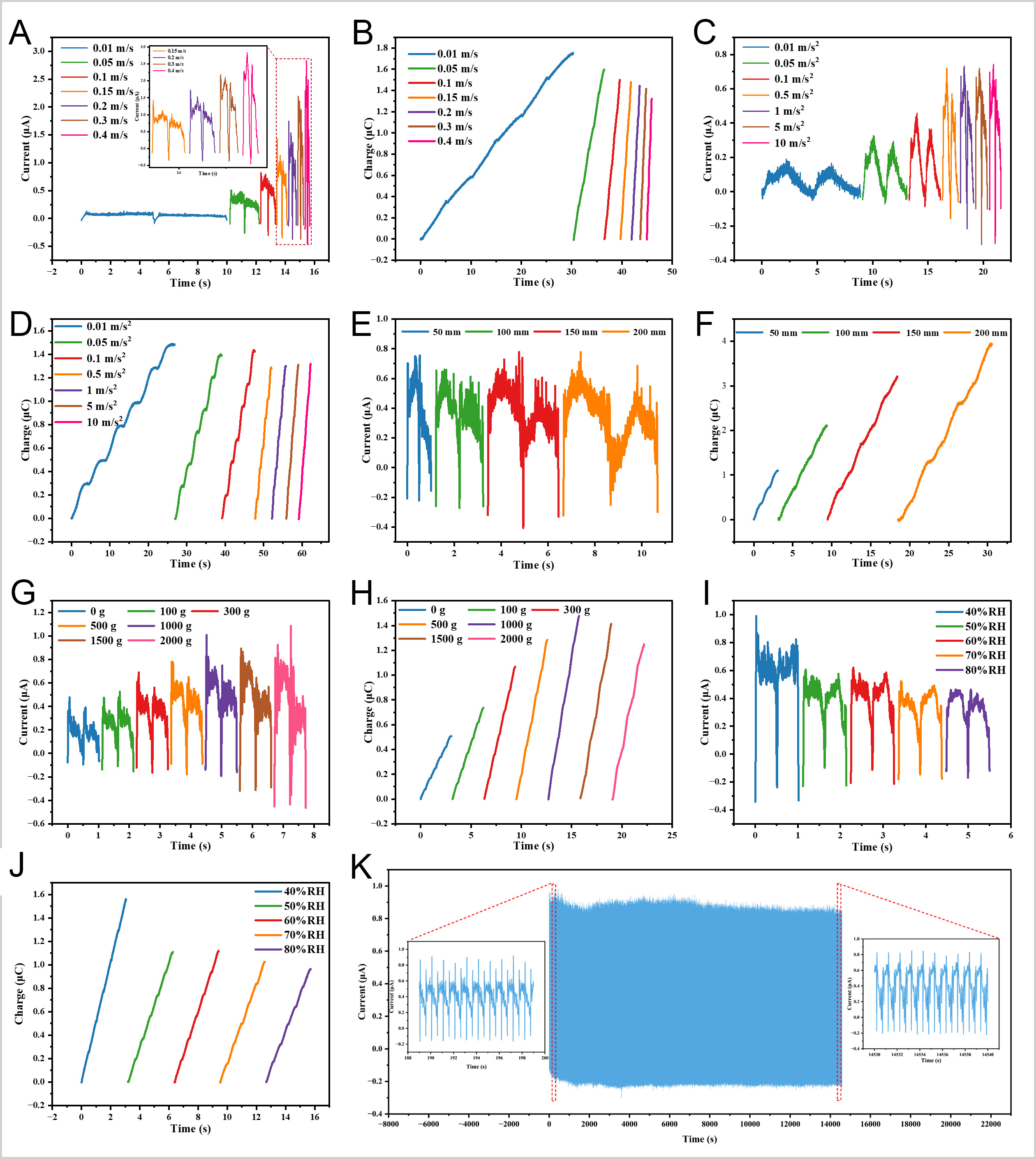
Figure 3. The Influence of Testing Conditions on the Output Performance of KF DC-TENG. (A) Current and (B) charge transfer of KF DC-TENG under different accelerations, (C) current and (D) charge transfer of KF DC-TENG under different velocities, (E) current and (F) charge transfer of KF DC-TENG under different displacement distances, (G) current and (H) charge transfer of KF DC-TENG under different weights, (I) current and (J) charge transfer of KF DC-TENG under different humidities, (K) current of KF DC-TENG after 14,000 friction cycles. TENG: Triboelectric nanogenerator; KF DC-TENG: knitted fabric-based direct current TENG.
As shown in Figure 3E and F, increasing the displacement distance increases the total collected charge while the peak current remains essentially unchanged. This is because the peak current is proportional to speed, and changing only the displacement does not affect speed. A longer displacement provides more time for air breakdown during unidirectional motion, thereby increasing the total collected charge. Besides, as previously mentioned, increasing the number of knitting courses of the friction electrode reduces the output due to decreased pressure. To verify this, weights were used to test the effect of pressure on the KF DC-TENG output [Figure 2A], and the results confirmed that increasing the applied weight enhances the contact between the fabric and FEP film, thereby improving the output performance. As presented in Figure 3G and H, both the peak current and the collected charge increased with the added weight, consistent with the prior analysis. However, when the weight reached 2 kg, the collected charge declined due to deformation of the unsupported acrylic plate, which reduced contact intimacy between the FEP film and the fabric. Furthermore, the fabric naturally maintains a moisture absorption and desorption equilibrium with the external environment and the human body during the wearing process. As shown in Figure 3I and J, the output continuously decreases with increasing humidity, as higher humidity accelerates charge dissipation in the air and thus reduces the total charge involved in air breakdown. We also evaluated the output performance after water washing. Daily laundering conditions were simulated using tap water and laundry detergent. As shown in Supplementary Figure 12, the output variation was negligible, indicating good washing resistance. The durability test indicated that after 14,000 consecutive cycles, the current output remained essentially unchanged, demonstrating excellent stability [Figure 3K]. All related voltages for these tests are provided in Supplementary Figures 13-15, showing trends consistent with current and charge measurements.
As shown in Figure 4A and Supplementary Figure 16, the power management circuit comprises three parts: the TENG that provides energy, the self-powered switch, and a buck circuit. Since the buck converter operates by continuous switching to regulate the output voltage, the self-powered switch is designed to automatically control the power supply via a rational circuit design. The self-powered switch consists of three electronic components [Supplementary Figure 17]: a high-voltage ceramic capacitor, a Zener diode, and a thyristor. The thyristor conducts only when the gate is forward biased relative to the cathode. Therefore, the operation sequence is as follows: First, the power source charges capacitor C1, for which a low-capacitance, high-voltage ceramic capacitor is chosen. This choice not only prevents the capacitor from being damaged by high voltage during TENG charging but also allows the capacitor to reach a high voltage more rapidly. Second, when the voltage of capacitor C1 reaches the breakdown voltage of the Zener diode D1, the Zener diode conducts, thereby causing the gate and cathode of the thyristor to conduct. As a result, the entire thyristor conducts, discharging the energy stored in capacitor C1 into the subsequent buck circuit. The thyristor then turns off and waits for C1’s voltage to reach the breakdown voltage of the Zener diode again before turning on once more. The frequency of this self-powered switch is determined by the relationship between the capacitance of C1 and the breakdown voltage of the Zener diode. Additionally, the current through resistor R in the buck circuit can be explained in three stages [Supplementary Figure 18]. Stage 1: When the self-powered switch is on, current flows from C1 to charge capacitor C2 and supply power to resistor R. Due to the blocking action of diode D2, the current cannot pass through D2 at this stage. Stage 2: After the charge in C1 is depleted and the thyristor turns off, inductor L induces an electromotive force in the same direction as that of C1, continuing to charge C2 and supply power to R. The current then flows through D2 back to the inductor. Stage 3: Once the energy in L is exhausted, C2 serves as the power source and continues to supply R. Although these three stages may appear discrete, they are in fact part of a continuous and cyclic process. When the switching frequency is sufficiently high, the current stabilizes and becomes effectively direct current. It should be noted that an electrometer cannot accurately measure transferred charge under pulsed signals [Supplementary Figure 19A and B]. However, with an inductance value of 1 μH, the charge measured by the electrometer is essentially consistent with the integral of the pulsed current. Therefore, the transferred charge is evaluated by integrating the pulsed current [Supplementary Figure 19C and D].
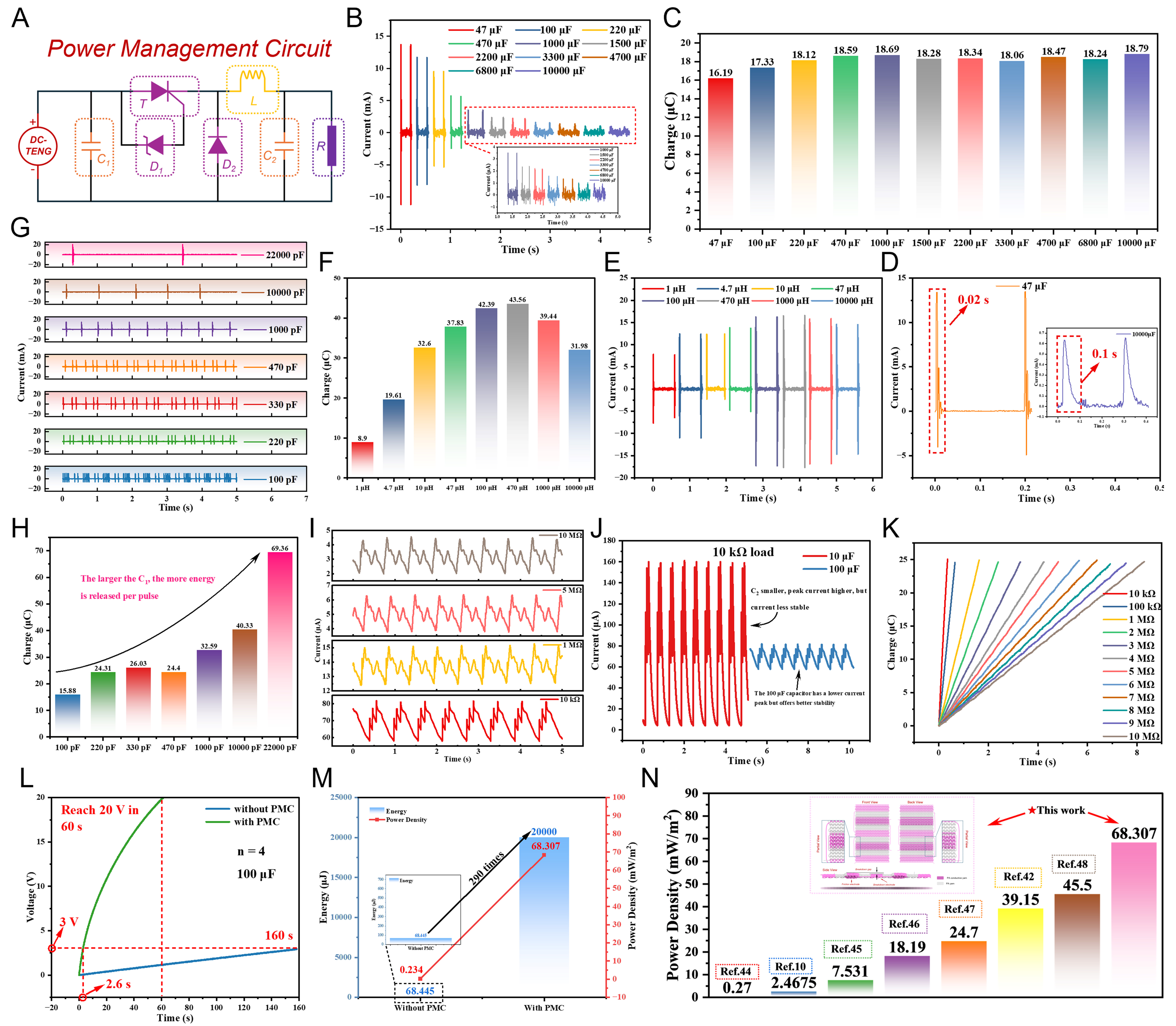
Figure 4. Research on Power Management Circuit. (A) Power management circuit, (B) Current and (C) Charge of the PMC under different capacitance values of C2, (D) Discharge time of the PMC with C2 capacitance values of 47 μF and 10,000 μF, (E) Current and (F) Charge under different inductance values of L, (G) Number of pulse currents and (H) Charge under different capacitance values of C1, (I) current of the PMC at different loads when C2 = 100 μF, (J) Current comparison of the PMC with C2 capacitance values of 10 μF and 100 μF under a load of 10 kΩ, (K) Charge of the PMC under different loads, (L) Comparison of charging time for a 100 μF capacitor with and without the PMC, (M) Comparison of charging energy with and without the PMC, (N) Comparison of the output of the fabric-based TENG with other fabric-based TENGs[10,42,44-48]. TENG: Triboelectric nanogenerator; KF DC-TENG: knitted fabric-based direct current TENG; PMC: power management circuit.
Figure 4B shows the current output when resistor R is replaced by an electrometer. Without the resistor, the current output appears as pulses. As the capacitance of C2 increases, the peak current decreases, but the charge transferred by each pulse current remains essentially unchanged [Figure 4C and Supplementary Figure 20]. A larger capacitance of C2 also results in a longer pulse duration [Figure 4D], which in turn extends the time required for the thyristor to turn off and for the voltage of C1 to reach the breakdown voltage of the Zener diode again. Furthermore, the movement speed of the KF DC-TENG affects the charge transferred within a given time. To investigate this, the linear motor speed was varied (total displacement distance per cycle: 100 mm, 1 Hz = 0.1 m/s). As shown in Supplementary Figure 21, as the movement frequency increases, the time between two pulse currents shortens, while the charge transfer of each pulse current remains essentially unchanged. The increase in speed allows the voltage of C1 to reach the breakdown voltage of the Zener diode more quickly, thereby enabling the PMC to generate more pulse currents in the same time. However, since the capacitance of C1 remains unchanged, the total amount of charge released each time the switch opens stays the same [Supplementary Figure 21B]. When the fabric output is insufficient to drive the PMC, no pulse current is generated [Supplementary Figure 21C]. Moreover, the size of inductor L also affects the output, and several different inductors were used to test their impact on the output performance of the PMC as shown in Figure 4E and F, and Supplementary Figure 22. Different inductance values produced output oscillations of varying degrees. To reduce oscillations and the increased resistance brought by high inductance values [Supplementary Figure 23 and Supplementary Note 5], an inductor of 10 μH was selected. As demonstrated in Figure 4G, reducing the capacitance of C1 increases the number of pulses generated within a given time, as a smaller capacitance allows faster charging and more rapid attainment of the Zener breakdown voltage. However, a larger capacitance stores more energy at the same voltage [Figure 4H and Supplementary Figure 24]. When C1 = 22,000 pF, the pulse current reaches
When the TENG is employed to power electronic components, its discontinuous output during the motion process necessitates the use of a capacitor before connecting to the load. Consequently, the ability of the TENG to charge a capacitor is of critical importance. Figure 5A illustrates the circuit used to evaluate the charging performance of the TENG. As shown in Figure 5B, smaller capacitances result in faster charging rates. For example, a 10 μF capacitor can be charged to 5 V within 50 s by a single unit of the KF DC-TENG. As the number of knitted units in the KF DC-TENG increases, the charging speed further improves [Figure 5C]. Since the KF DC-TENG has a direct current output, it can directly power electronic components without any rectification equipment [Figure 5D]. When we manually rubbed a single unit of the
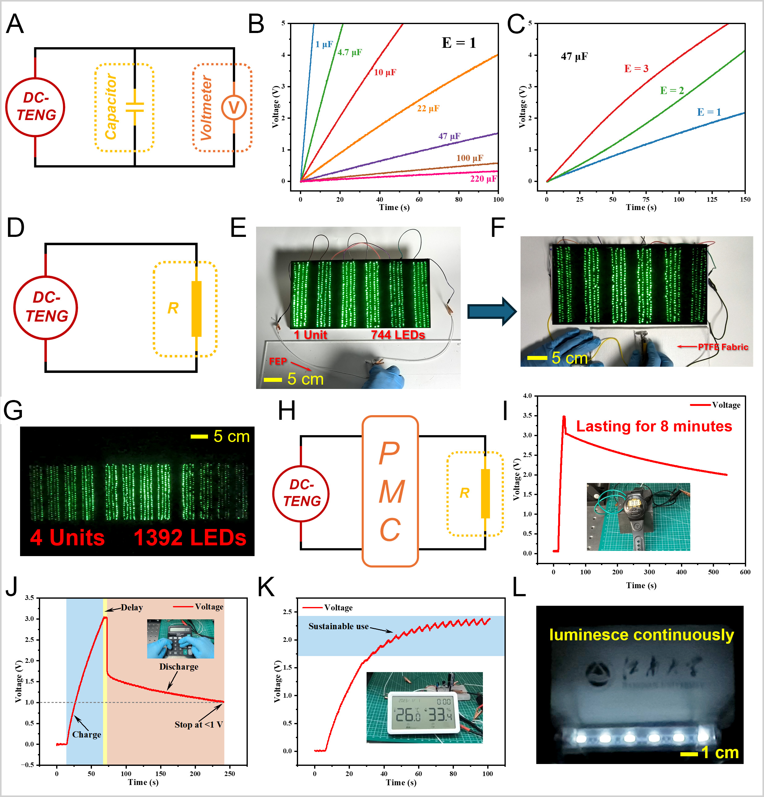
Figure 5. Actual Practical Applications. (A) Schematic diagram of the capacitor charging circuit, (B) voltage plots for charging different capacitors with KF DC-TENG when E = 1, (C) voltage plots for charging a 47 μF capacitor with KF DC-TENG at different E values, (D) circuit diagram of DC-TENG directly powering a resistor, (E) manually lighting up 744 LEDs with KF DC-TENG when E = 1, (F) lighting up 744 LEDs with KF DC-TENG by friction with PTFE fabric when E = 1, (G) lighting up 1392 LEDs with a four unit KF DC-TENG, (H) circuit diagram of DC-TENG powering electronic devices through a PMC, powering (I) a wristwatch, (J) a calculator, (K) a hygrometer, and (L) a 1.5 W commercial light bulb through the PMC. Photos in (E-G), (I-L) are taken by the authors. TENG: Triboelectric nanogenerator; KF DC-TENG: knitted fabric-based direct current TENG; PMC: power management circuit; LEDs: light emitting diodes.
After integration with the PMC [Figure 5H], a four-unit KF DC-TENG (A = 4, B = 6, C = 1, speed 0.4 m/s, stroke 100 mm, C1 = 100 pF, unchanged in subsequent tests) only took 17 s to charge a 1,000 μF capacitor, which enabled a watch (3 V) to operate continuously for 8 min [Figure 5I and Supplementary Movie 5]. Additionally, a calculator (1.5 V) could also be powered and used, and it stopped working only when the capacitor voltage dropped below 1 V [Figure 5J and Supplementary Movie 6]. Furthermore, the energy generated by the KF DC-TENG after the PMC could power a hygrometer (1.5 V) continuously [Figure 5K and Supplementary Movie 7]. A commercial 1.5 W LED light could be continuously lit without noticeable flickering (speed 0.8 m/s), as shown in Figure 5L and Supplementary Movie 8. These applications demonstrate the excellent mechanical energy harvesting capability and promising application potential of the KF DC-TENG with the PMC.
CONCLUSIONS
In summary, this work presents a KF DC-TENG constructed from conventional interlock and plain stitch structures, aiming to realize wearable energy harvesting via air breakdown in textiles. The KF DC-TENG is designed via knitting CAD and manufactured by whole-garment knitting technology, which avoids complicated post-processing and supports direct one-step fabrication. The structural asymmetry between double-needle-bed and single-needle-bed knitting enables dual-sided energy conversion, offering a universal design strategy for knitted direct current generators. This study provides a simple, scalable, and wearable approach for fabric-based energy harvesting, with good compatibility to industrial textile manufacturing. Benefiting from its softness, breathability, and structural stability, the KF DC-TENG shows promising potential for wearable electronics. With further structural optimization and system integration, this kind of knitted direct current generator is expected to offer a practical pathway toward self-powered wearable systems and smart textiles in the future.
DECLARATIONS
Authors’ contributions
Responsible for the study design, data collection and manuscript drafting: Wang, W.; Wang, K.
Participated in the experiments and data sorting: Su, Z.; Wei, J.
Provided resources and guidance: Cong, H.; Jiang, G.
Provided technical support and experimental materials: Jiang, H.; Zhao, G.; Guo, H.
Supervised the project, analyzed the data and revised the manuscript critically: Wen, Z.; Chen, L.; Chen, C.; Ma, P.
All authors read and approved the final manuscript.
Availability of data and materials
Data will be made available on reasonable request from the corresponding author.
AI and AI-assisted tools statement
Not applicable.
Financial support and sponsorship
This work is supported by the National Natural Science Funds of China (52303055), the Wuxi Science and Technology Development Fund Project (K20241035), the Fundamental Research Funds for the Central Universities (JUSRP202401043), the Natural Science Foundation of Jiangsu Province (BK20221094), the Wuxi Light of Taihu Science and Technology Project (Y20242210), and the fellowship of China Postdoctoral Science Foundation (2022TQ0123).
Conflicts of interest
All authors declared that there are no conflicts of interest.
Ethical approval and consent to participate
Not applicable.
Consent for publication
Not applicable.
Copyright
© The Author(s) 2026.
Supplementary Materials
REFERENCES
1. Aouedi, O.; Vu, T.; Sacco, A.; et al. A survey on intelligent internet of things: applications, security, privacy, and future directions. IEEE. Commun. Surv. Tutorials. 2025, 27, 1238-92.
2. Qi, W.; Xu, X.; Qian, K.; Schuller, B. W.; Fortino, G.; Aliverti, A. A review of AIoT-based human activity recognition: from application to technique. IEEE. J. Biomed. Health. Inform. 2025, 29, 2425-38.
3. He, L.; Gao, Y.; Yao, S.; et al. A Multifunctional power textile based on interfacial electrostatic breakdown. Adv. Funct. Mater. 2025, 35, e09809.
4. Dong, K.; Wang, Y. C.; Deng, J.; et al. A Highly stretchable and washable all-yarn-based self-charging knitting power textile composed of fiber triboelectric nanogenerators and supercapacitors. ACS. Nano. 2017, 11, 9490-9.
5. Wang, S.; Gao, J.; Lu, F.; et al. Human motion recognition by a shoes-floor triboelectric nanogenerator and its application in fall detection. Nano. Energy. 2023, 108, 108230.
6. Dong, K.; Wu, Z.; Deng, J.; et al. A stretchable yarn embedded triboelectric nanogenerator as electronic skin for biomechanical energy harvesting and multifunctional pressure sensing. Adv. Mater. 2018, 30, e1804944.
7. Pan, Y.; Xu, K.; Wang, R.; Wang, H.; Chen, G.; Wang, K. Lithium-ion battery condition monitoring: a frontier in acoustic sensing technology. Energies 2025, 18, 1068.
8. Attia, P. M.; Moch, E.; Herring, P. K. Challenges and opportunities for high-quality battery production at scale. Nat. Commun. 2025, 16, 611.
10. Kwak, S. S.; Kim, H.; Seung, W.; Kim, J.; Hinchet, R.; Kim, S. W. Fully stretchable textile triboelectric nanogenerator with knitted fabric structures. ACS. Nano. 2017, 11, 10733-41.
11. Wang, Z. L. Triboelectric nanogenerators as new energy technology and self-powered sensors - principles, problems and perspectives. Faraday. Discuss. 2014, 176, 447-58.
12. Wang, S.; Lin, L.; Wang, Z. L. Triboelectric nanogenerators as self-powered active sensors. Nano. Energy. 2015, 11, 436-62.
13. Wu, H.; Wang, J.; Fu, S.; et al. A constant current triboelectric nanogenerator achieved by hysteretic and ordered charge migration in dielectric polymers. Energy. Environ. Sci. 2023, 16, 5144-53.
14. Gao, S.; Wei, H.; Wang, J.; et al. Self-powered system by a suspension structure-based triboelectric-electromagnetic-piezoelectric hybrid generator for unifying wind energy and vibration harvesting with vibration attenuation function. Nano. Energy. 2024, 122, 109323.
15. Zhang, C.; Zhou, L.; Cheng, P.; et al. Surface charge density of triboelectric nanogenerators: theoretical boundary and optimization methodology. Appl. Mater. Today. 2020, 18, 100496.
16. Sun, D.; Song, W.; Li, C.; et al. High-voltage direct current triboelectric nanogenerator based on charge pump and air ionization for electrospinning. Nano. Energy. 2022, 101, 107599.
17. Cui, S.; Liu, D.; Yang, P.; et al. Triboelectric-material-pairs selection for direct-current triboelectric nanogenerators. Nano. Energy. 2023, 112, 108509.
18. Zhao, Z.; Zhou, L.; Li, S.; et al. Selection rules of triboelectric materials for direct-current triboelectric nanogenerator. Nat. Commun. 2021, 12, 4686.
19. Li, S.; Zhao, Z.; Liu, D.; et al. A self-powered dual-type signal vector sensor for smart robotics and automatic vehicles. Adv. Mater. 2022, 34, e2110363.
20. Wang, Z.; Zhang, Z.; Chen, Y.; et al. Achieving an ultrahigh direct-current voltage of 130 V by semiconductor heterojunction power generation based on the tribovoltaic effect. Energy. Environ. Sci. 2022, 15, 2366-73.
21. Lin, S.; Lu, Y.; Feng, S.; Hao, Z.; Yan, Y. A high current density direct-current generator based on a moving van der waals schottky diode. Adv. Mater. 2019, 31, e1804398.
23. Xu, C.; Yu, J.; Huo, Z.; Wang, Y.; Sun, Q.; Wang, Z. L. Pursuing the tribovoltaic effect for direct-current triboelectric nanogenerators. Energy. Environ. Sci. 2023, 16, 983-1006.
24. Qiao, G.; Wang, J.; Yu, X.; Jia, R.; Cheng, T.; Wang, Z. L. A bidirectional direct current triboelectric nanogenerator with the mechanical rectifier. Nano. Energy. 2021, 79, 105408.
25. Fu, S.; He, W.; Wu, H.; et al. High output performance and ultra-durable dc output for triboelectric nanogenerator inspired by primary cell. NanoMicro. Lett. 2022, 14, 155.
26. Wang, J.; Wu, Z.; Pan, L.; et al. Direct-current rotary-tubular triboelectric nanogenerators based on liquid-dielectrics contact for sustainable energy harvesting and chemical composition analysis. ACS. Nano. 2019, 13, 2587-98.
27. Zhang, C.; Zhou, T.; Tang, W.; Han, C.; Zhang, L.; Wang, Z. L. Rotating‐disk‐based direct‐current triboelectric nanogenerator. Adv. Energy. Mater. 2014, 4, 1301798.
29. Yang, Y.; Zhang, H.; Wang, Z. L. Direct‐current triboelectric generator. Adv. Funct. Mater. 2014, 24, 3745-50.
30. Liu, D.; Yin, X.; Guo, H.; et al. A constant current triboelectric nanogenerator arising from electrostatic breakdown. Sci. Adv. 2019, 5, eaav6437.
31. Chen, C.; Guo, H.; Chen, L.; et al. Direct current fabric triboelectric nanogenerator for biomotion energy harvesting. ACS. Nano. 2020, 14, 4585-94.
32. Wang, F.; Tian, J.; Ding, Y.; et al. A universal managing circuit with stabilized voltage for maintaining safe operation of self-powered electronics system. iScience 2021, 24, 102502.
33. Wu, H.; Shan, C.; Fu, S.; et al. Efficient energy conversion mechanism and energy storage strategy for triboelectric nanogenerators. Nat. Commun. 2024, 15, 6558.
34. Wang, Q.; Hu, D.; Huang, X.; et al. Achieving high performance of triboelectric nanogenerators via voltage boosting strategy. Adv. Funct. Mater. 2024, 34, 2409088.
35. Li, M.; Zhang, Y.; Wang, H.; et al. Performance enhancement of self-charging system by combining triboelectric nanogenerators and dielectric capacitors. Nano. Energy. 2024, 119, 109073.
36. Cheng, G.; Lin, Z. H.; Lin, L.; Du, Z. L.; Wang, Z. L. Pulsed nanogenerator with huge instantaneous output power density. ACS. Nano. 2013, 7, 7383-91.
37. Harmon, W.; Bamgboje, D.; Guo, H.; Hu, T.; Wang, Z. L. Self-driven power management system for triboelectric nanogenerators. Nano. Energy. 2020, 71, 104642.
38. Liu, W.; Wang, Z.; Wang, G.; et al. Switched-capacitor-convertors based on fractal design for output power management of triboelectric nanogenerator. Nat. Commun. 2020, 11, 1883.
39. Yang, J.; Yang, F.; Zhao, L.; et al. Managing and optimizing the output performances of a triboelectric nanogenerator by a self-powered electrostatic vibrator switch. Nano. Energy. 2018, 46, 220-8.
40. Wang, Z.; Liu, W.; Hu, J.; et al. Two voltages in contact-separation triboelectric nanogenerator: From asymmetry to symmetry for maximum output. Nano. Energy. 2020, 69, 104452.
41. Cheng, R.; Dong, K.; Chen, P.; et al. High output direct-current power fabrics based on the air breakdown effect. Energy. Environ. Sci. 2021, 14, 2460-71.
42. Cheng, R.; Ning, C.; Chen, P.; et al. Enhanced output of on‐body direct‐current power textiles by efficient energy management for sustainable working of mobile electronics. Adv. Energy. Mater. 2022, 12, 2201532.
43. Yi, Z.; Liu, D.; Zhou, L.; et al. Enhancing output performance of direct-current triboelectric nanogenerator under controlled atmosphere. Nano. Energy. 2021, 84, 105864.
44. Jiang, Y.; An, J.; Liang, F.; et al. Knitted self-powered sensing textiles for machine learning-assisted sitting posture monitoring and correction. Nano. Res. 2022, 15, 8389-97.
45. Dong, S.; Xu, F.; Sheng, Y.; Guo, Z.; Pu, X.; Liu, Y. Seamlessly knitted stretchable comfortable textile triboelectric nanogenerators for E-textile power sources. Nano. Energy. 2020, 78, 105327.
46. Wang, Z.; Ruan, Z.; Ng, W. S.; et al. Integrating a triboelectric nanogenerator and a zinc‐ion battery on a designed flexible 3D spacer fabric. Small. Methods. 2018, 2, 1800150.
47. He, M.; Du, W.; Feng, Y.; et al. Flexible and stretchable triboelectric nanogenerator fabric for biomechanical energy harvesting and self-powered dual-mode human motion monitoring. Nano. Energy. 2021, 86, 106058.
Cite This Article
How to Cite
Download Citation
Export Citation File:
Type of Import
Tips on Downloading Citation
Citation Manager File Format
Type of Import
Direct Import: When the Direct Import option is selected (the default state), a dialogue box will give you the option to Save or Open the downloaded citation data. Choosing Open will either launch your citation manager or give you a choice of applications with which to use the metadata. The Save option saves the file locally for later use.
Indirect Import: When the Indirect Import option is selected, the metadata is displayed and may be copied and pasted as needed.
About This Article
Special Topic
Copyright

Data & Comments
Data
0


Comments
Comments must be written in English. Spam, offensive content, impersonation, and private information will not be permitted. If any comment is reported and identified as inappropriate content by OAE staff, the comment will be removed without notice. If you have any queries or need any help, please contact us at [email protected].