

Waste-asphalt-derived carbon interlayer enabling uniform CuS deposition for advanced ferricyanide/polysulfide flow batteries
 0
0 Graphical Abstract
Abstract
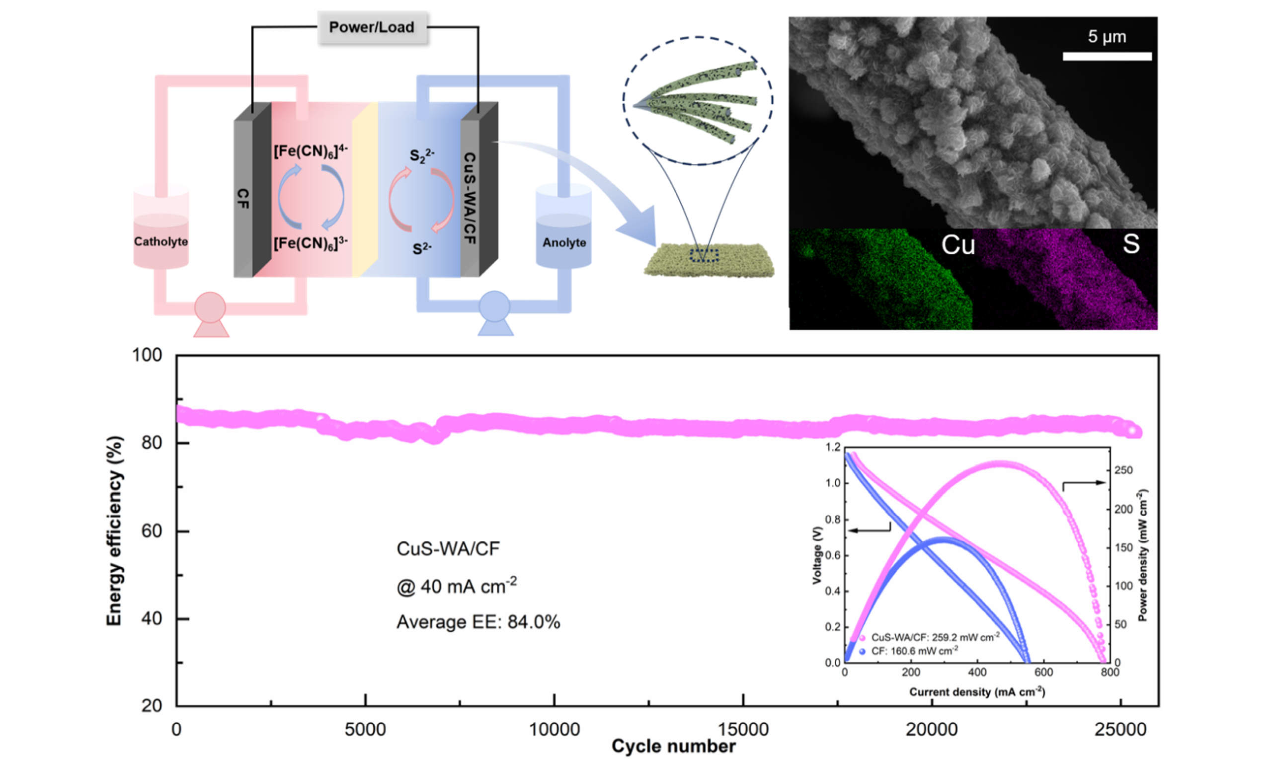
Alkaline ferrocyanide-polysulfide redox flow batteries (Fe/S RFBs) have emerged as a promising candidate for grid-scale energy storage, primarily owing to their low raw material costs, intrinsic operational safety, and the inherent decoupling of power and energy in their design. Yet the intrinsically sluggish S22-/S2- chemistry restricts their power output and cycling durability. To tackle this, we developed a copper sulfide (CuS) and waste-asphalt-derived carbon co-modified carbon felt electrode (CuS-WA/CF), where waste-asphalt pyrolytic carbon serves as an interlayer to guide uniform copper electrodeposition. Subsequently, sulfidation converts the copper into well-dispersed CuS nanoparticles. This rational design increases the specific surface area by approximately 8.4-fold (from 9.55 to 80.46 m2 g-1) and markedly boosts electrochemical activity and conductivity. As a result, the assembled Fe/S RFB with CuS-WA/CF as the anode delivers a peak power density of 259.2 mW cm-2, which is 61.4% higher than the pristine-CF counterpart. At 40 mA cm-2, the cell maintained an average energy efficiency (EE) of 77.7% across 10,000 constant-current charge-discharge cycles. In a separate test using a higher-concentration ferrocyanide catholyte and excess anolyte, the cell delivered an average EE of 84.0% across 25,000 capacity-limited cycles. Beyond the performance gains, this work turns waste asphalt into a functional carbon source, offering a low-cost, scalable route toward the practical deployment of Fe/S RFBs for renewable integration.
Keywords


 Download PDF
INTRODUCTION
Fossil fuels (coal, oil, and natural gas), which account for over 80% of primary energy consumption, still dominate the global energy mix. Their combustion not only depletes finite fossil resources but also contributes to climate change and air pollution[1,2]. Renewables like wind and solar have grown rapidly, yet their output is inherently variable: the sun sets, the wind lulls, and grid operators are left scrambling to balance supply and demand, often wasting excess power in the process[3,4]. Redox flow batteries (RFBs) offer a particularly promising solution to the above challenges[5,6]. Unlike conventional closed-cell batteries which store energy directly in the electrode materials, RFBs store energy in liquid electrolytes. Moreover, these electrolytes are contained in separate external tanks. This architecture means that power and energy capacity become independent of each other. This feature is especially valuable for grid-scale energy storage. RFBs also bring other practical benefits. For example, they are intrinsically safe, tolerate deep discharging, and typically have a long cycle life[7-10]. Among the various RFB chemistries, the all-vanadium redox flow battery (VRFB) has been the most commercially advanced with several megawatt-scale installations already in operation worldwide[11-14]. Despite this progress, the VRFBs still face notable limitations that hinder wider deployment. Vanadium is a relatively scarce and costly metal, which causes higher system costs. Meanwhile, the energy density which is determined by the concentration of active species is another issue as the current vanadium electrolytes only reach about 25 Wh L-1. Furthermore, the strongly acidic electrolyte creates a harsh environment that can promote the degradation of electrodes, membranes, bipolar plates, and other cell components, thereby compromising the long-term durability of VRFBs[15,16]. These drawbacks have motivated considerable research into alternative chemistries that are affordable, more energy-dense, and less corrosive to cell hardware[17,18].
This is where the alkaline ferrocyanide/polysulfide redox flow battery (Fe/S RFB) enters the picture. Its active materials, ferrocyanide and polysulfide, are cheap, abundantly available, and dissolve readily in alkaline electrolyte (up to 1.0 M or higher)[19-22]. The trouble is, the S22-/S2- couple at the anode suffers from a large kinetic barrier, causing sluggish charge transfer and severe polarization that cripple efficiency and cycling stability[23,24]. Therefore, the development of efficient electrocatalytic materials to accelerate the charge-transfer process of the sulfide redox pair is of paramount importance for advancing this battery system[25].
Recent efforts have explored a variety of transition-metal sulfides (e.g., CoS, WS2, and MoS2) and their carbon-based composites as electrocatalysts for modifying carbon felt (CF) electrodes to boost polysulfide conversion[26-28]. For instance, Liu and co-workers modified CF with 1T-MoS2, achieving an EE of 80.82% at a current density of 20 mA cm-2 over 2,500 cycles[28]. Despite these encouraging results, many of the reported catalytic materials suffer from drawbacks such as complicated preparation procedures, high raw-material costs, or limited density of active sites, which collectively impede their simultaneous fulfillment of high activity, long-term durability, and economic viability for practical applications.
To address these challenges, we herein propose a novel and sustainable strategy that repurposes waste asphalt, which is an abundant industrial byproduct, as a carbon precursor, combined with electro-deposited copper sulfide (CuS), to construct a highly active interface on CF. In our approach, waste asphalt mixed with KOH was uniformly coated onto CF and subsequently subjected to high-temperature pyrolysis. The KOH in our approach serves a dual role. It creates abundant defect sites through chemical activation and markedly improves the hydrophilic character of the carbon surface, thus facilitating electrolyte penetration. Following pyrolysis, copper was electrodeposited onto the pyrolytic carbon layer. The resulting material was then immersed in K2S solution to convert the deposited copper into CuS nanoparticles. This yields the waste-asphalt pyrolytic carbon and electrodeposited CuS co-modified CF (denoted as CuS-WA/CF).
Characterization results confirm that CuS nanoparticles are uniformly anchored on the carbon fibers. The specific surface area is significantly enlarged. Wettability by the alkaline electrolyte is also greatly enhanced. Electrochemical tests show that the CuS-WA/CF electrode displays superior activity toward the S22-/S2- reaction. It reduces the electrochemical polarization and promotes interfacial charge transfer.
We set the anode to operate on the reversible S22-/S2- redox couple. With the CuS-WA/CF electrode, the alkaline Fe/S RFB shows much less polarization and reaches a peak power density of 259.2 mW cm-2. Under long cycling at 40 mA cm-2, it delivers an average energy efficiency (EE) of 77.7% and an average voltage efficiency (VE) of 78.0%. More remarkably, under the capacity-limited short-cycle protocol, the cell completed 25,000 cycles with an average EE of 84.0%. These results confirm the practical potential of the CuS-WA/CF electrode for advanced alkaline Fe/S RFBs.
MATERIALS AND METHODS
Materials
The waste asphalt was supplied by Hunan Expressway Group Co., Ltd. and originated from the asphalt milling residue of damaged road surfaces. CF with a thickness of 5.5 mm and a bulk density ranging from 0.08-0.11 g cm-3 was purchased from Liaoning Jingu Carbon Materials Co., Ltd. (China). All chemical reagents, including potassium hydroxide (KOH, analytical reagent (AR) grade, 85%), copper sulfate pentahydrate (CuSO4·5H2O, AR, 99%), potassium ferrocyanide trihydrate (K4[Fe(CN)6]·3H2O, AR, 99.5%), sodium ferrocyanide decahydrate (Na4[Fe(CN)6]·10H2O, 99.5%), potassium sulfide (K2S, 40%), and sulfuric acid (H2SO4, 98%) were sourced from Sinopharm Chemical Reagent Co., Ltd. (China). The perfluorosulfonic acid ion-exchange membrane was obtained from Shandong Dongyue Future Hydrogen Energy Material Co., Ltd. It was pretreated by heating in 1.0 M KOH solution at 80 °C for 1.5 h, followed by rinsing with deionized water to remove residual alkali. The resulting K+-form membrane was then stored in deionized water prior to use.
Fabrication of the CuS-WA/CF electrode
The detailed preparation process for the CuS-WA/CF electrode is schematically depicted. Briefly, a pristine piece of CF was first immersed in an asphalt solution for 1 min and then dried at 100 °C for 5 h. Subsequently, the felt was soaked in an ethanol solution containing 2.0 M KOH for 5 min, followed by drying at 90 °C for 6 h. The treated sample was then placed in a tube furnace and annealed at 700 °C for 2 h under an inert atmosphere. After cooling to ambient temperature, the product was rinsed thoroughly with deionized water and dried at 100 °C for 5 h. In the next step, copper electrodeposition was performed using an electrochemical workstation in a plating electrolyte consisting of 0.8 M CuSO4 dissolved in 1.0 M H2SO4 solution. The deposition was conducted at a constant current density of 1 mA cm-2 for 12 h. After electroplating, the electrode was washed with deionized water and dried at 100 °C for 5 h. It was then immersed in a 2.0 M K2S solution for 30 min to convert the deposited copper into CuS, followed by another drying step at 100 °C for 5 h. The resulting electrode, denoted as CuS-WA/CF, was finally obtained and used for subsequent characterization and cell tests.
Materials characterization
The crystalline phases of the pristine CF and the CuS-WA/CF composite were examined by X-ray diffraction (XRD) at a scanning rate of 5° min-1. Surface morphologies and elemental compositions were observed using a scanning electron microscope (SEM, JEOL JSM-7900F) equipped with an energy-dispersive X-ray spectrometer (EDS). X-ray photoelectron spectroscopy (XPS) analysis was carried out on an AXIS ULTRA DLD spectrometer. The extent of surface defects was evaluated by Raman spectroscopy with a 532 nm excitation laser. Specific surface areas were determined by the Brunauer-Emmett-Teller (BET) method. Contact angles, which reflect the wettability of the electrode surfaces, were measured with a Harke-SPCAXD instrument.
Electrochemical measurements
Cyclic voltammetry (CV) and electrochemical impedance spectroscopy (EIS) were carried out using a VSP BioLogic electrochemical workstation. For the CV experiments, a standard three-electrode configuration was adopted. The pristine CF or the CuS-WA/CF composite (1.0 × 1.0 cm) served as the working electrode, a platinum mesh as the counter electrode, and a saturated calomel electrode (SCE) as the reference electrode. The CV scans were recorded at a scan rate of 10 mV s-1 within a potential window ranging from -1.2 V to
Cell assembly and electrochemical testing
The alkaline Fe/S RFB was assembled using a K+-type perfluorosulfonic acid membrane as the ion-exchange membrane. A piece of pristine CF with a geometric area of 13.5 cm2 served as the cathode, whereas the anode was either pristine CF or CuS-WA/CF of the same area. Cell performance was first assessed using a catholyte with a relatively low [Fe(CN)6]4- concentration (0.1 M K4[Fe(CN)6] + 2.0 M KOH, 20.0 mL) and an anolyte of 20.0 mL of 2.0 M K2S in 1.0 M KOH. After establishing the baseline behavior, the [Fe(CN)6]4- concentration in the catholyte was increased to 0.8 M (0.4 M K4[Fe(CN)6] + 0.4 M Na4[Fe(CN)6] + 1.0 M KOH, 20.0 mL), while the anolyte volume was increased to 60.0 mL of 2.0 M K2S in 1.0 M KOH.
Galvanostatic intermittent titration technique (GITT) measurements, rate-capability tests, polarization measurements, long-term cycling tests, and capacity-limited short-cycle tests were performed using a NEWARE battery testing system (CT-4008Q-5V6A-S1-F, Shenzhen Neware Technology Electronics Co., Ltd.). The charge-discharge, GITT, rate-capability, and polarization measurements were conducted using 20.0 mL of a 0.8 M [Fe(CN)6]4- catholyte containing 0.4 M K4[Fe(CN)6], 0.4 M Na4[Fe(CN)6], and 1.0 M KOH, together with 60.0 mL of an anolyte containing 2.0 M K2S and 1.0 M KOH. More specifically, the GITT was performed at a current density of 40 mA cm-2 with a relaxation time of
Recovery of cell performance via electrolyte renewal
To recover the cell performance, both the anolyte and catholyte were first drained from their respective reservoirs. The cell components were then rinsed with 1.0 M KOH solution to remove any residual active species. Subsequently, a cleaning solution consisting of 2.0 M K2S and 1.0 M KOH was introduced into both the positive and negative compartments, with 60.0 mL injected into each side. This solution was circulated through the cell and reservoirs by a peristaltic pump for 12 h to fully dissolve the insulating solid sulfur that had precipitated on the cathode side. Once this circulation was complete, we drained the cleaning solution and rinsed the cell again with 1.0 M KOH. Fresh catholyte containing [Fe(CN)6]4- was then fed into the positive reservoir and fresh anolyte containing K2S was introduced into the negative side. The cell was now ready for the next charge-discharge test. The entire procedure was carried out without disassembling the cell.
Theoretical calculations
Spin-polarized density functional theory (DFT) calculations were carried out using the Vienna ab initio Simulation Package (VASP)[29,30] with a plane-wave basis set and the projector augmented-wave method[31,32]. The exchange-correlation energy was treated by using the Perdew-Burke-Ernzerhof (PBE) functional within the generalized gradient approximation (GGA)[33]. The plane-wave energy cutoff was set to 500 eV, and the Brillouin zone was sampled using a Γ-centered 2 × 2 × 1 Monkhorst-Pack k-point mesh generated with VASPKIT[34,35]. All structures were optimized until the residual force on each atom was less than 0.03 eV Å-1, with an electronic energy convergence criterion of 10-5 eV. Dispersion interactions were accounted for using Grimme’s DFT-D3 correction[36]. A vacuum layer of 15 Å was used along the c direction to minimize interactions between periodic images. The adsorption energy (Eads) was calculated according to:
where Etotal, Especies, and Esurface represent the total energy of the adsorbate-surface system, the energy of the isolated sulfur species, and the energy of the clean surface, respectively. A more negative Eads indicates more favorable adsorption.
RESULTS AND DISCUSSION
We electrodeposited copper onto CF that had been pre-impregnated with waste-asphalt pyrolytic carbon. A subsequent sulfidation step converted the copper into CuS to yield the CuS-WA/CF electrode [Figure 1A]. SEM images reveal the surface morphology changes. Pristine CF shows smooth, bare fibers with a limited number of active sites for redox reactions [Figure 1B and C]. Direct copper plating on bare CF (yielding Cu-CF) produces large, smooth copper crystals at sparse nucleation sites [Supplementary Figure 1]. This morphology reduces the specific surface area and limits accessible active sites for polysulfide conversion. The waste-asphalt-derived carbon interlayer changes this picture entirely. It promotes dense and uniform Cu nucleation during electrodeposition. After K2S sulfidation, the deposited Cu particles are converted to CuS without substantial morphological disruption. As can be seen in Figure 1D and E, the resulting CuS-WA/CF electrode exhibits a uniform, fine-grained CuS layer on the carbon fibers. The elemental maps
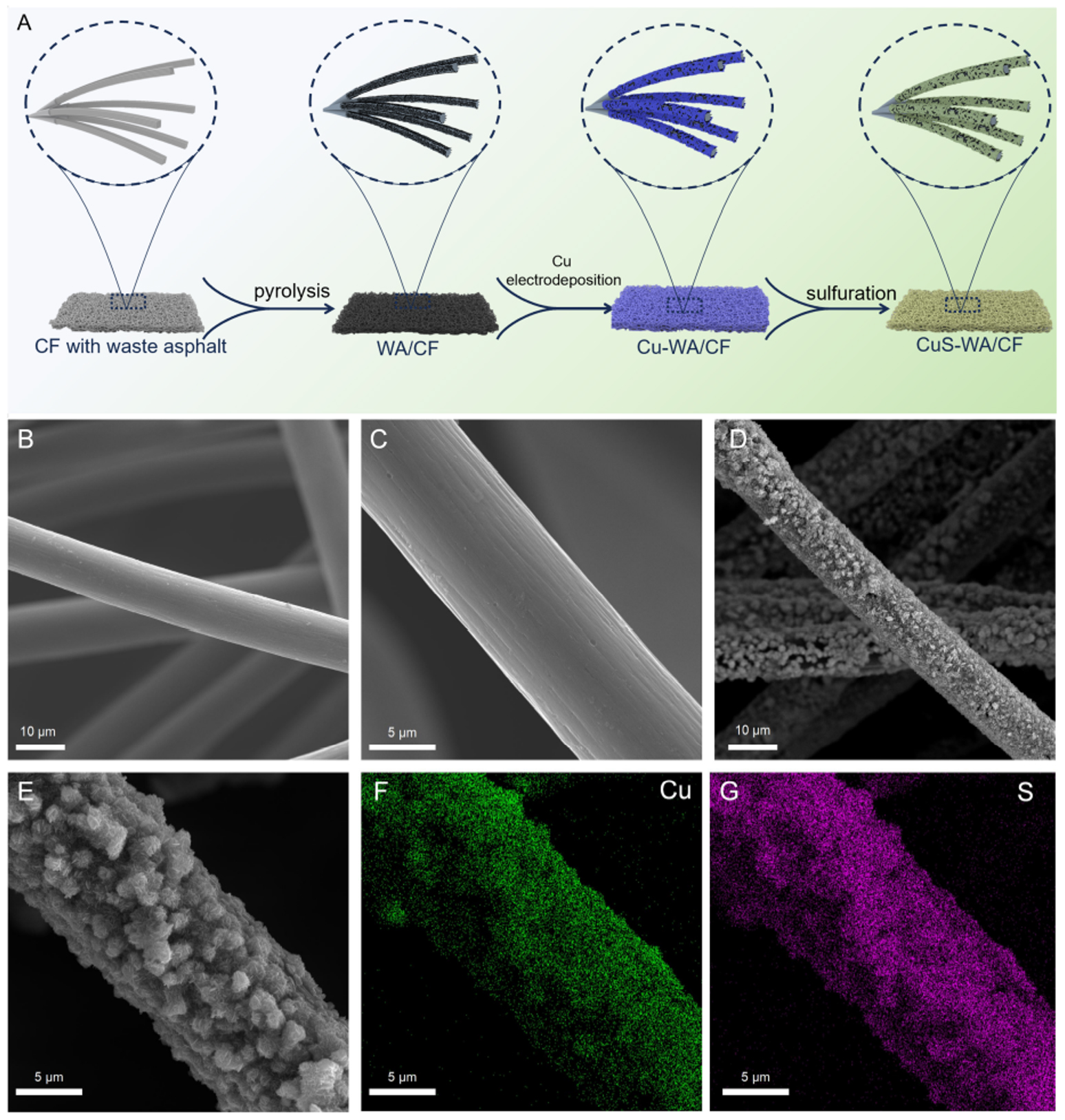
Figure 1. Morphological evolution and elemental analysis following electrode modification. (A) Step-by-step preparation scheme for the CuS-WA/CF composite electrode. (B and C) Low- and high-magnification SEM images of the as-received carbon felt (pristine CF). (D and E) SEM images of CuS-WA/CF, where the carbon fibers are conformally covered by a dense CuS layer. (F and G) EDS elemental mapping of Cu and S, demonstrating homogeneous distribution of both elements throughout the modified electrode.
XRD patterns were used to examine the crystal structure of the modified electrode [Figure 2A]. The XRD pattern of CuS-WA/CF exhibits well-defined diffraction peaks at 29.2°, 31.7°, 32.7°, and 47.8°, which can be readily indexed to the (102), (103), (006), and (110) planes of hexagonal covellite CuS (Powder Diffraction File No. 01-073-6495). The absence of impurity peaks suggests that the sulfidation reaction proceeded to completion and that phase-pure CuS was successfully deposited onto the CF substrate. We further analyzed the surface chemical composition of CuS-WA/CF using XPS spectroscopy. The survey spectrum in Figure 2B shows clear signals for carbon, sulfur, and copper. The carbon signal originates from both the underlying CF support and the waste-asphalt-derived carbon interlayer, whereas the S and Cu signals arise from the outermost CuS coating. The presence of all three elements is consistent with the expected structure of the electrode. Raman spectroscopy was employed to assess changes in carbon defect density upon modification [Figure 2C]. Both samples display the characteristic D band (~1,350 cm-1) and G band (~1,580 cm-1) of carbon materials. For pristine CF, the intensity ratio ID/IG is calculated to be 1.12, whereas for CuS-WA/CF this ratio increases to 1.42. The higher ID/IG value points to a lower degree of graphitization and a greater abundance of structural defects in the modified electrode. Such defects are generally beneficial for electrochemical performance, as they can provide additional active sites for reaction and may also contribute to an expanded electrochemically active surface area. To quantify the change in surface area, we performed nitrogen adsorption-desorption measurements [Figure 2D]. According to BET results, CuS-WA/CF reaches a specific surface area of 80.46 m2 g-1, which is almost nine times higher than the value of pristine CF
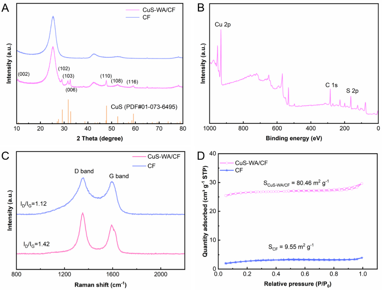
Figure 2. Structural characterization of pristine CF and CuS-WA/CF electrodes. (A) XRD patterns. (B) Full-range XPS survey spectra. (C) Raman spectra. (D) N2 adsorption-desorption isotherms.
As reported in an earlier study, wettability also plays a key role in electrode performance[37]. A hydrophilic surface helps the electrolyte penetrate fully and contact well with the active sites. Such good contact boosts fast electrochemical kinetics. Herein, the contact angle measurements provide direct evidence. Pristine CF shows a contact angle of 114° [Supplementary Figure 2A], indicating the hydrophobic feature. The CuS-WA/CF electrode is almost completely wetted by water, with a contact angle approaching 0°
CV was employed to evaluate the electrochemical performance of the pristine CF and CuS-WA/CF electrodes toward polysulfide redox reactions. It is known that multiple polysulfide species are present in alkaline electrolytes. But well-defined redox peaks mainly corresponding to the S22-/S2- couple are observed in the CV profiles. As presented in Figure 3A, the peak separation (ΔEp) for the pristine CF was as large as
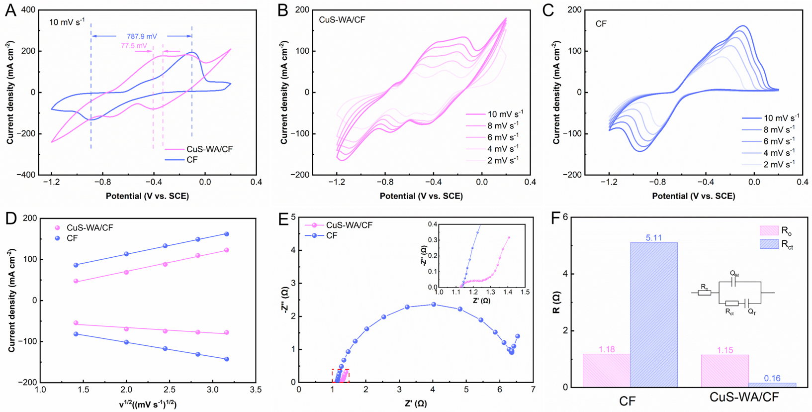
Figure 3. Electrochemical characterization of pristine CF and CuS-WA/CF electrodes in 0.1 M K2S + 1.0 M KOH electrolyte. (A) CV curves at 10 mV s-1. (B and C) CV curves for pristine CF and CuS-WA/CF collected at varying scan rates. (D) Peak current density versus the square root of scan rate. (E) Nyquist plots measured at open-circuit potential. (F) Quantitative comparison of the equivalent circuit resistance values derived from EIS fitting.
The superior conductivity and charge-transfer kinetics of CuS-WA/CF were further corroborated by EIS [Figure 3E and F, Supplementary Table 1]. The ohmic resistance (Ro) values are 1.18 and 1.15 Ω for pristine CF and CuS-WA/CF, respectively. The nearly unchanged Ro indicates comparable cell and electrolyte resistance. The charge-transfer resistance (Rct) of CuS-WA/CF was determined to be 0.16 Ω, which is 96.9% lower than that of the pristine CF (5.11 Ω). This marked reduction in Rct unequivocally demonstrates that the uniformly dispersed CuS particles anchored on the pyrolysis carbon skeleton promote faster interfacial charge transfer on the electrode, accelerating the oxidation-reduction kinetics of the S22-/S2- couple.
We assembled two sets of alkaline Fe/S RFBs to test the CuS-WA/CF electrode. One used pristine CF as the anode. The other used CuS-WA/CF. All other components and conditions were kept identical. The charge-discharge profiles were recorded at 40 mA cm-2 [Figure 4A]. The CuS-WA/CF cell charges at a notably lower voltage than the pristine-CF cell. The discharge voltages of the two cells are nearly the same. This difference in charging overpotential means that CuS-WA/CF substantially reduces polarization. The polarization and power density curves confirm this [Figure 4B]. The CuS-WA/CF cell reaches 259.2 mW cm-2 in peak power density. The pristine-CF cell reaches only 160.6 mW cm-2. We used GITT to examine the overpotential during cycling [Figure 4C]. CuS-WA/CF significantly cuts the voltage loss. At 40 mA cm-2, the CuS-WA/CF cell deviated from the equilibrium potential by only 83 mV, which is considerably lower than the
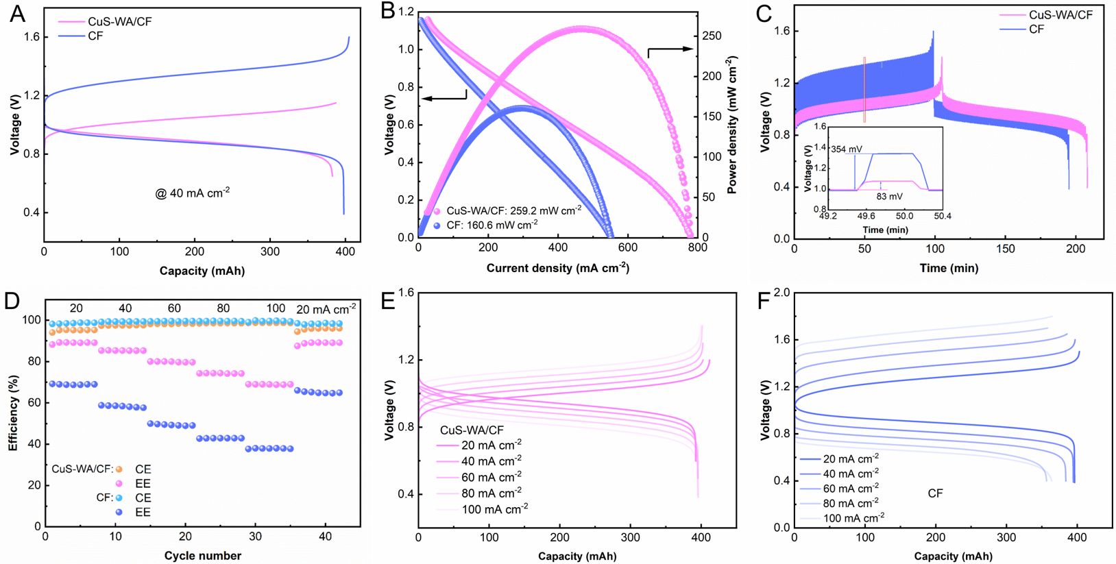
Figure 4. Comparative cell performance of alkaline Fe/S RFBs with pristine CF and CuS-WA/CF anodes. (A) Representative charge-discharge curves at 40 mA cm-2. (B) Polarization curves and the corresponding power density curves derived from them. (C) GITT curves. (D) Rate capability tested at progressively increasing current densities from 20 to 100 mA cm-2. (E) Charge-discharge profiles of CuS-WA/CF-based cell across all tested current densities. (F) Charge-discharge profiles of pristine-CF-based cell across all tested current densities. All measurements shown in this figure were performed using 20.0 mL of a 0.8 M [Fe(CN)6]4- catholyte containing 0.4 M K4[Fe(CN)6], 0.4 M Na4[Fe(CN)6], and 1.0 M KOH, together with 60.0 mL of an anolyte containing 2.0 M K2S and 1.0 M KOH.
Rate capability tests covered 20 to 100 mA cm-2. As shown in Figure 4D, the pristine CF and CuS-WA/CF cells exhibit comparable Coulombic efficiencies (CE) over the current density range of 20-100 mA cm-2, with only minor differences between them. In contrast, the CuS-WA/CF cell delivers markedly higher energy efficiencies, indicating that its performance advantage primarily arises from reduced polarization. At
We began our evaluation with a relatively dilute ferrocyanide catholyte (0.1 M [Fe(CN)6]4-), which served as a baseline condition for comparing the two electrode materials. At 40 mA cm-2, the cell with the CuS-WA/CF anode reached a maximum EE of 84.6% and a VE of 85.0%. The improvements are 19.0% and 19.5%, respectively, over the pristine CF cell [Figure 5A and B]. As cycling continued, we observed a gradual decline in performance. Closer examination suggested that this decay was primarily associated with the crossover of polysulfide species from the anolyte through the membrane into the catholyte compartment, where they eventually precipitated as insulating sulfur, although electrode polarization may also have contributed to the performance loss. This observation motivated us to design a cycling protocol to distinguish electrolyte degradation from possible electrode degradation. Taking advantage of the flow-battery architecture, we replaced the electrolyte solution without disassembling the cell. In this way, the electrode remained intact and could be tested again with fresh electrolytes. When the EE of the CuS-WA/CF cell dropped to 69.0% during operation, the electrolyte-renewal procedure, including redissolution of the precipitated sulfur (details in the Section “Recovery of cell performance via electrolyte renewal”), was performed. As a result, the EE jumped back to 81.2%. Over the entire 10,000 cycles, the CuS-WA/CF cell maintained average values of 77.7% for EE and 78.0% for VE. The substantial recovery in cell performance after electrolyte replacement suggests that electrolyte degradation was a major contributor to the performance decay and that the CuS-WA/CF electrode maintained good stability under the conditions examined, although electrode-related degradation cannot be completely excluded. We compared the present system with recently reported polysulfide-based flow batteries. As summarized in Supplementary Figure 3, the CuS-WA/CF cell exhibits outstanding power output with notably prolonged cycling durability[22,24,28,38-41].
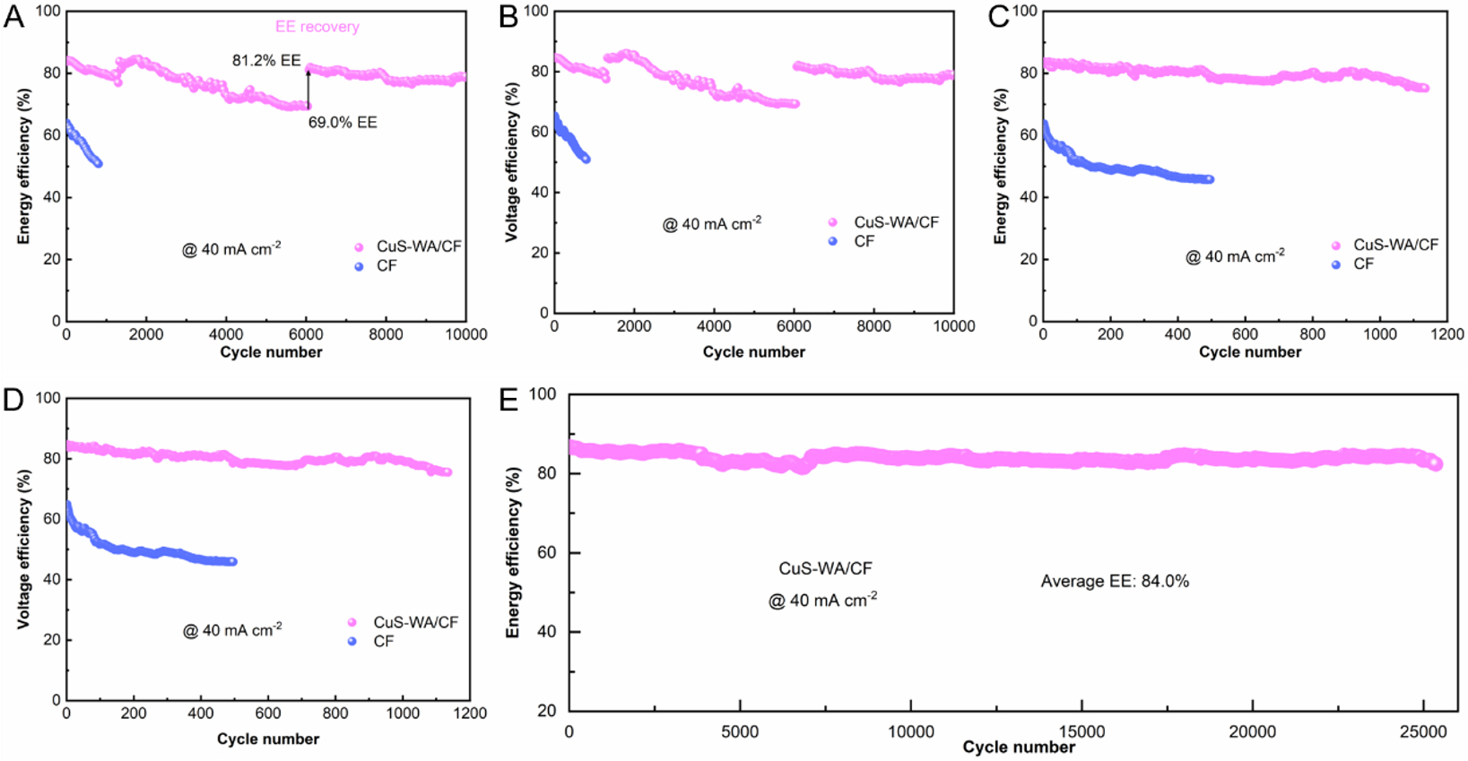
Figure 5. Cycling performance of alkaline Fe/S RFBs with different anodes. (A and B) EE and VE vs. cycle number for cells with 0.1 M [Fe(CN)6]4- catholyte. (C and D) Cycling data for cells with 0.8 M [Fe(CN)6]4- catholyte. (E) Capacity-controlled short-cycle tests of the CuS-WA/CF cell at 50% SOC.
Then we raised the catholyte concentration to 0.8 M [Fe(CN)6]4-. It is known that higher concentration gives better energy density. However, it also makes mass transport and reaction kinetics more challenging. The electrode must operate under more demanding conditions. The CuS-WA/CF electrode performed well at this elevated concentration. The cell with CuS-WA/CF as the anode delivered an average EE of 79.7% and a VE of 80.1% over 1,100 consecutive cycles [Figure 5C and D]. The pristine CF cell, on the other hand, performed poorly under the same conditions. Its average EE and VE were only 49.9% and 50.1%, respectively, and the cell failed completely after just 500 cycles.
Encouraged by these results, we pushed the CuS-WA/CF electrode harder using a capacity-limited short-cycle protocol. This test was designed to accelerate aging and reveal the electrode’s durability. The cell was first charged to a 50% SOC. Each cycle then delivered and accepted a fixed capacity of
To investigate the origin of the enhanced activity of CuS-WA/CF toward the S22-/S2- redox couple, spin-polarized DFT calculations were performed to compare the adsorption behavior of the sulfur species on CuS-WA/CF and pristine CF. The optimized adsorption configurations on CuS-WA/CF are shown in
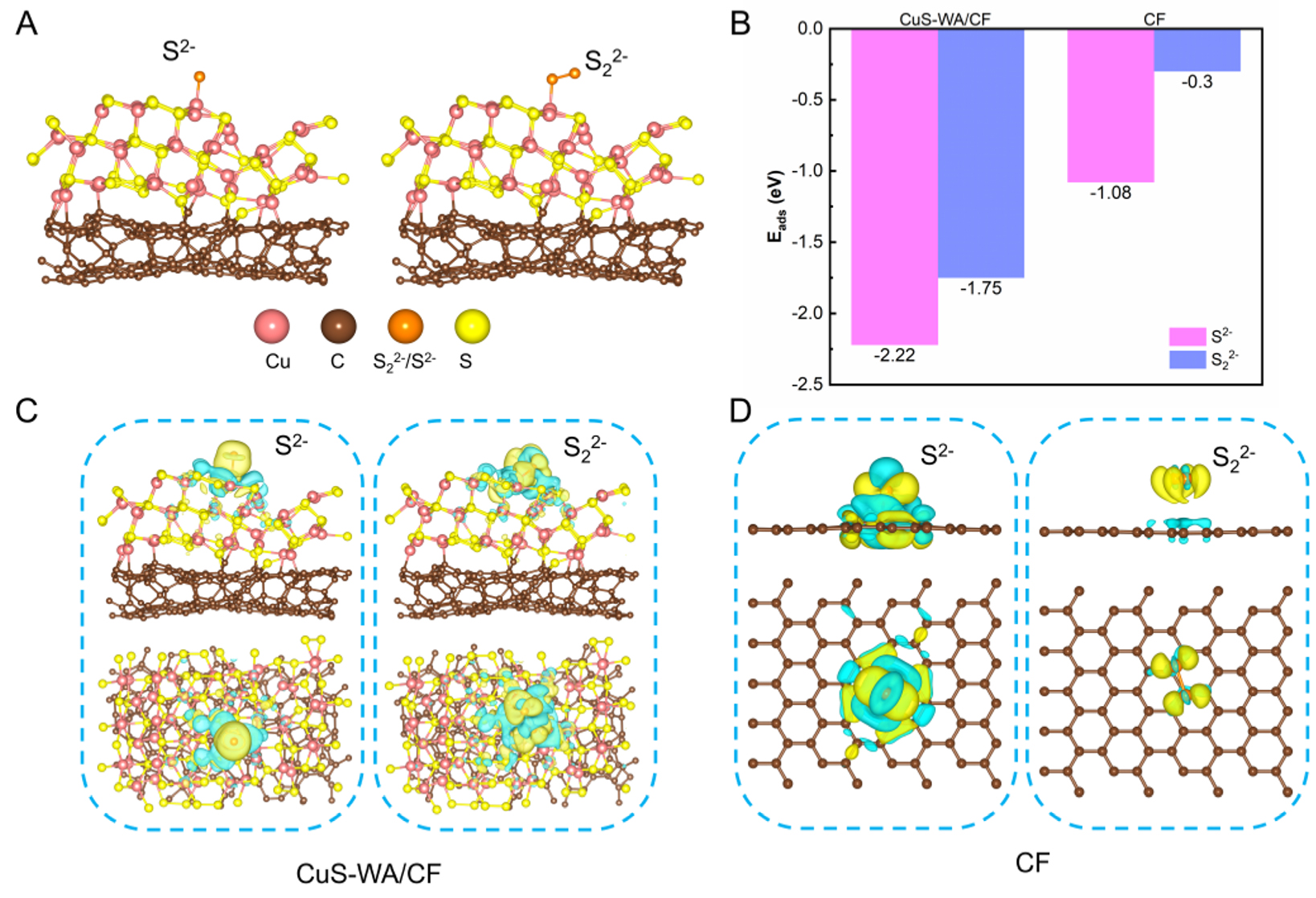
Figure 6. DFT analysis of sulfur-species adsorption on electrodes. (A) Optimized adsorption configurations of S2- and S22- on the basal plane of CuS-WA/CF. (B) Calculated adsorption energies (Eads) of S2- and S22- on the surface of CuS-WA/CF and pristine CF. Differential charge-density maps for the adsorption of both sulfur species on (C) CuS-WA/CF and (D) pristine CF. Yellow and cyan isosurfaces indicate electron accumulation and depletion, respectively.
CONCLUSION
In summary, we have developed a CuS-WA/CF composite electrode using a three-step fabrication route: waste-asphalt-derived pyrolytic carbon coating, copper electrodeposition, and final sulfidation to CuS. The pyrolytic carbon interlayer plays a critical role in this approach. It provides abundant defect sites that promote uniform copper nucleation across the fiber surface. Without this layer, copper forms sparse, coarse crystals on bare CF. After sulfidation, the resulting CuS particles serve as active centers for S22-/S2- redox conversion.
Electrochemical tests confirm the performance improvements of CuS-WA/CF compared to pristine CF. The peak-to-peak separation in CV curves narrows from 787.9 to 77.5 mV, while the charge-transfer resistance extracted from EIS decreases from 5.11 to 0.16 Ω. In full alkaline Fe/S RFBs, the CuS-WA/CF anode delivers 259.2 mW cm-2 in peak power density, a marked improvement over the 160.6 mW cm-2 for the cell with pristine CF as the anode. The CuS-WA/CF electrode also enables excellent cycling stability in the Fe/S RFB. The cell maintains an average EE of 77.7% over 10,000 cycles, and 84.0% EE across 25,000 cycles at
Besides, this work shows that waste asphalt can be reused as a functional carbon precursor. The pyrolytic carbon interlayer strategy for tuning metal position uniformity may extend to other electrocatalytic systems. Overall, the CuS-WA/CF electrode offers a promising step toward high-performance and low-cost alkaline Fe/S RFBs for grid-scale energy storage.
DECLARATIONS
Authors’ contributions
Conception and design of the work: Jia, C.; Xu, Z.; Zheng, J.
Data acquisition and analysis: Xu, Z.; Li, Q.; Zhang, Q.; Xie, S.
Data interpretation: Xu, Z.; Xu, J.; Ding, M.
Funding Acquisition: Jia, C.
Manuscript writing and revising: Xu, Z.; Ding, M.
Supervision: Zheng, J.; Jia, C.
Availability of data and materials
The original contributions presented in this study are included in the article/Supplementary Materials. Further data are available from the corresponding authors upon reasonable request.
AI and AI-assisted tools statement
Not applicable.
Financial support and sponsorship
This work was supported by the National Key Research and Development Program of China (2024YFE0116300), the Key Research and Development Program of Hunan (2023SK2053) and the National Natural Science Foundation of China (22209015).
Conflicts of interest
All authors declared that there are no conflicts of interest.
Ethical approval and consent to participate
Not applicable.
Consent for publication
Not applicable.
Copyright
© The Author(s) 2026.
Supplementary Materials
REFERENCES
1. Chen, P.; Wu, Y.; Meng, J.; et al. The heterogeneous role of energy policies in the energy transition of Asia-Pacific emerging economies. Nat. Energy. 2022, 7, 588-96.
2. Xu, X.; Zhang, X.; Zou, Y.; et al. Integrated carbon and nitrogen management for cost-effective environmental policies in China. Science 2025, 388, 1098-103.
3. Zhao, J.; Li, F.; Zhang, Q. Impacts of renewable energy resources on the weather vulnerability of power systems. Nat. Energy. 2024, 9, 1407-14.
4. Hu, Y.; Jiang, H.; Zhang, C.; et al. Advancing solar and wind penetration in China through energy complementarity. Nature 2026, 653, 1060-8.
5. Zhang, H.; Lu, W.; Li, X. Progress and perspectives of flow battery technologies. Electrochem. Energy. Rev. 2019, 2, 492-506.
6. Song, M.; Chen, H.; Sun, J.; et al. Enhanced stability of extended viologen anolyte for aqueous organic redox flow batteries via an electron-withdrawing imidazole group. Energy. Storage. Mater. 2026, 89, 105253.
7. Huang, S.; Yuan, Z.; Salla, M.; et al. A redox-mediated zinc electrode for ultra-robust deep-cycle redox flow batteries. Energy. Environ. Sci. 2023, 16, 438-45.
8. Wei, Z.; Chen, Z.; Wang, Y.; et al. Catalytic electrolytes enable fast reaction kinetics and temperature adaptability for aqueous zinc-bromine flow batteries. Nat. Commun. 2025, 16, 10097.
9. Yuan, Z.; Liang, L.; Dai, Q.; et al. Low-cost hydrocarbon membrane enables commercial-scale flow batteries for long-duration energy storage. Joule 2022, 6, 884-905.
10. He, C.; Zhang, Y.; Zhang, S.; et al. Aqueous iron-based redox flow batteries for large-scale energy storage. Natl. Sci. Rev. 2025, 12, nwaf218.
11. Rao, H.; Yang, F.; Pan, L.; et al. Numerical insights into the interplay between mass transport and parasitic hydrogen evolution in vanadium redox flow batteries. Appl. Energy. 2026, 410, 127565.
12. Wang, Z.; Sun, J.; Shen, J.; et al. Operando quantitatively analyses of polarizations in all-vanadium flow batteries. J. Energy. Chem. 2025, 105, 178-84.
13. Li, T.; Xing, F.; Liu, T.; et al. Cost, performance prediction and optimization of a vanadium flow battery by machine-learning. Energy. Environ. Sci. 2020, 13, 4353-61.
14. Cheng, T.; Qi, S.; Jiang, Y.; et al. Carbon structure regulation strategy for the electrode of vanadium redox flow battery. Small 2024, 20, 2400496.
15. Satola, B. Review—bipolar plates for the vanadium redox flow battery. J. Electrochem. Soc. 2021, 168, 060503.
16. Yuan, X. Z.; Song, C.; Platt, A.; et al. A review of all-vanadium redox flow battery durability: degradation mechanisms and mitigation strategies. Int. J. Energy. Res. 2019, 43, 6599-638.
17. Lei, J.; Yao, Y.; Huang, Y.; Lu, Y. A highly reversible low-cost aqueous sulfur-manganese redox flow battery. ACS. Energy. Lett. 2023, 8, 429-35.
18. Chong, F.; He, C.; Tu, Z.; et al. Organic molecular differential lock balancing transport-reaction kinetics for long-life alkaline zinc-based flow batteries. Adv. Funct. Mater. 2026, 36, e21073.
19. Zhang, J.; Zhou, W.; Zhao, D.; Lu, Y.; Chao, D. Aqueous sulfur-based redox flow battery. Nat. Rev. Electr. Eng. 2025, 2, 215-7.
20. Wang, F.; Luo, S.; Lei, J.; et al. Nonfluorinated membrane with a decentralized ion-transport network enables efficient and sustainable polysulfide redox flow batteries. Sci. Adv. 2025, 11, eaea0032.
21. Hu, L.; Zhou, T.; Wang, J.; et al. Materials strategies for S/Fe redox flow batteries: mechanisms, challenges and perspectives. Mater. Today. Energy. 2026, 60, 102354.
22. Gao, M.; Huang, S.; Zhang, F.; Lee, Y. M.; Huang, S.; Wang, Q. Successive ionic layer adsorption and reaction-deposited copper sulfide electrocatalyst for high-power polysulfide-based aqueous flow batteries. Mater. Today. Energy. 2020, 18, 100540.
23. Lan, J.; Zhang, S.; Yang, L.; et al. High-power polysulfide redox flow batteries via an interfacial electron field on a 2D mesoporous heterojunction. ACS. Nano. 2025, 19, 31699-708.
24. Yu, X.; Lin, Z.; Gao, H.; et al. Polysulfide-based aqueous redox flow batteries enhanced by carbon electrodes with S8/Sx2- redox pairs and hydrophilic carbon nanocuboids. ACS. Appl. Energy. Mater. 2025, 8, 3592-8.
25. Lei, J.; Zhang, Y.; Yao, Y.; et al. An active and durable molecular catalyst for aqueous polysulfide-based redox flow batteries. Nat. Energy. 2023, 8, 1355-64.
26. Ma, D.; Hu, B.; Wu, W.; et al. Highly active nanostructured CoS2/CoS heterojunction electrocatalysts for aqueous polysulfide/iodide redox flow batteries. Nat. Commun. 2019, 10, 3367.
27. He, X.; Xu, Z.; Dong, B.; et al. Orbital-regulated stepwise polysulfide catalysis enabled by Ni-Mn D-electron complementarity in aqueous polysulfide-based flow batteries. Adv. Energy. Mater. 2026, e71374.
28. Liu, R.; Yan, S.; Huang, X.; et al. Metallic-phase MoS2 nanosheets boost polysulfide redox kinetics to high-performance polysulfide-based flow batteries. Chem. Eng. J. 2026, 530, 173401.
30. Kohn, W.; Sham, L. J. Self-consistent equations including exchange and correlation effects. Phys. Rev. 1965, 140, A1133-8.
31. Kresse, G.; Furthmüller, J. Efficient iterative schemes for ab initio total-energy calculations using a plane-wave basis set. Phys. Rev. B. 1996, 54, 11169-86.
33. Perdew, J. P.; Burke, K.; Ernzerhof, M. Generalized gradient approximation made simple. Phys. Rev. Lett. 1996, 77, 3865-8.
34. Monkhorst, H. J.; Pack, J. D. Special points for brillouin-zone integrations. Phys. Rev. B. 1976, 13, 5188-92.
35. Wang, V.; Xu, N.; Liu, J.; Tang, G.; Geng, W. VASPKIT: a user-friendly interface facilitating high-throughput computing and analysis using VASP code. Comput. Phys. Commun. 2021, 267, 108033.
36. Grimme, S.; Antony, J.; Ehrlich, S.; Krieg, H. A consistent and accurate ab initio parametrization of density functional dispersion correction (DFT-D) for the 94 elements H-Pu. J. Chem. Phys. 2010, 132, 154104.
37. Lim, H.; Chae, S.; Yan, L.; et al. Crosslinked polyethyleneimine gel polymer interface to improve cycling stability of RFBs. Energy. Mater. Adv. 2022, 2022, 9863679.
38. Lou, X.; Fu, H.; Xu, J.; et al. Cost-effective membrane and advanced electrode for stable polysulfide-ferricyanide flow battery. Energy. Mater. Adv. 2022, 2022, 9865618.
39. Chen, Q.; Zhu, Y.; Zhang, S.; et al. Bislawsone as a robust redox mediator for high-performance aqueous polysulfide redox flow batteries. Joule 2026, 10, 102362.
40. Zhang, H.; Feng, Z.; Ding, T.; et al. Mn-Co dual-metal single-atom catalytic sites for boosted redox kinetics in aqueous polysulfide/ferricyanide flow batteries. Nano. Lett. 2025, 25, 11051-9.
Cite This Article
 Open Access
How to Cite
Download Citation
If you have the appropriate software installed, you can download article citation data to the citation manager of your choice. Simply select your manager software from the list below and click on download.
Export Citation File
Type of Import
Tips on Downloading Citation
Citation Manager File Format
Type of Import
Direct Import: When the Direct Import option is selected (the default state), a dialogue box will give you the option to Save or Open the downloaded citation data. Choosing Open will either launch your citation manager or give you a choice of applications with which to use the metadata. The Save option saves the file locally for later use.
Indirect Import: When the Indirect Import option is selected, the metadata is displayed and may be copied and pasted as needed.
About This Article
Special Topic
Copyright

Data & Comments
Data
0











Comments
Comments must be written in English. Spam, offensive content, impersonation, and private information will not be permitted. If any comment is reported and identified as inappropriate content by OAE staff, the comment will be removed without notice. If you have any queries or need any help, please contact us at [email protected].