


fig6
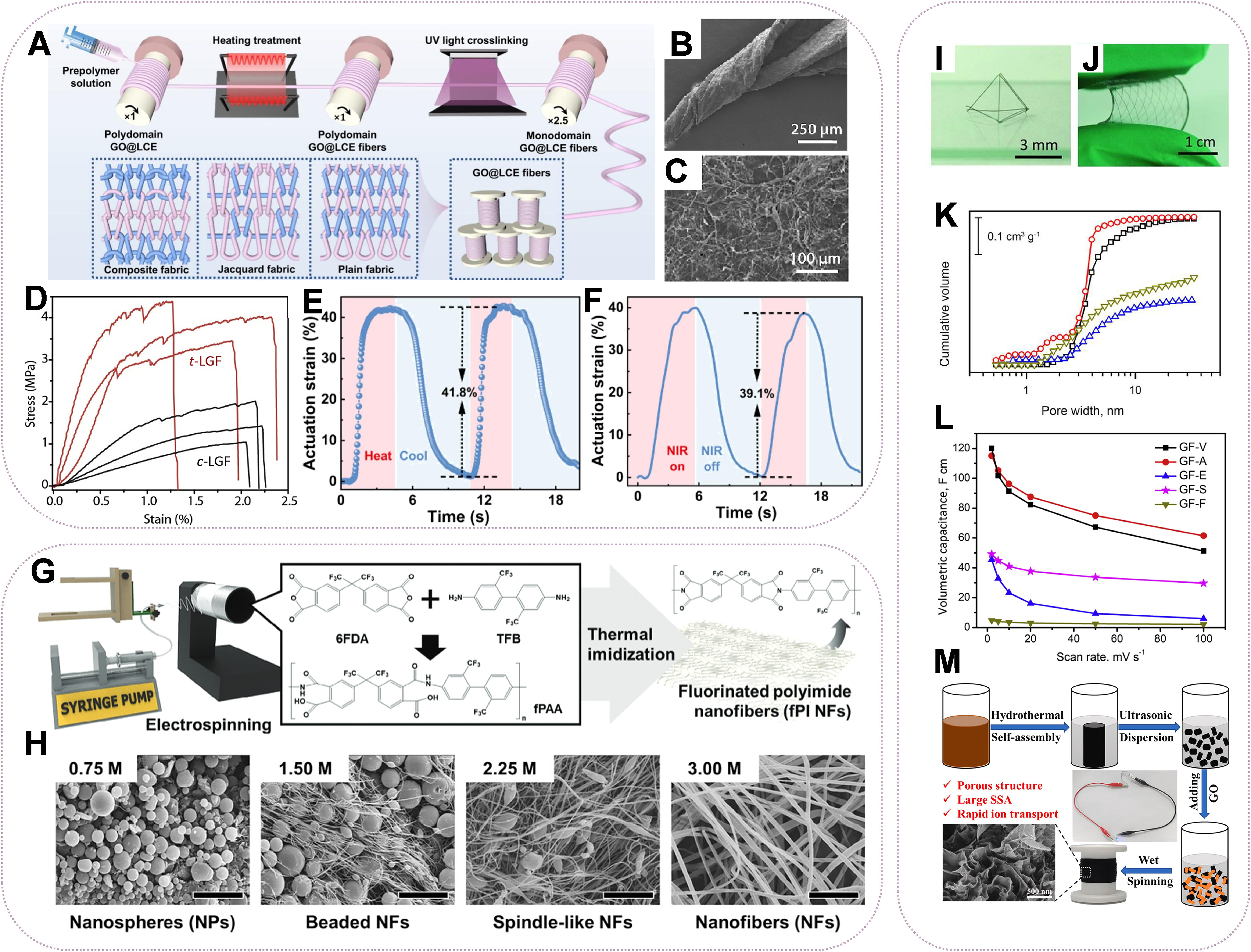
Figure 6. (A) Schematic diagram of the preparation process of GO@LCE fiber actuators. Reproduced with permission[82], Copyright © 2025 Elsevier; (B) and (C) SEM pictures of various LGF locations; (D) Stress-strain curves of c-LGF (red) and t-LGF (black). (B-D) are reprinted with permission from Ref.[83], Copyright © 2019 Elsevier; (E) The relationship between actuation strain and time under thermal stimulation; (F) The relationship between actuation strain and time under light stimulation. (E and F) are reprinted with permission from Ref.[82], Copyright © 2025 Elsevier; (G) Electrospinning fPAANFs to synthesize fPINFs; (H) SEM images of electrospun fPAANPs or NFs under various solution concentrations with scale bars indicating 10.0 μm. (G and H) are reprinted with permission from Ref.[84], Copyright © 2025 John Wiley and Sons; (I) The 3D geometric structures of GFs; (J) Photograph of GF network embedded in PDMS matrix. (I and J) are reprinted with permission from Ref.[85], Copyright © 2012 John Wiley and Sons; (K) The cumulative pore volume of rGO fibers obtained using different drying conditions from the same rGO hydrogel fibers; (L) The comparison of volumetric and gravimetric capacitances of rGO fibers determined at 2 mv·s-1. (K and L) are reprinted with permission from Ref.[86], Copyright © 2020 Elsevier; (M) Schematic illustration of the fabrication process for porous GFs. Reproduced with permission[87]. Copyright © 2025 Elsevier. GO: Graphene oxide; LCE: liquid crystal elastomer; SEM: scanning electron microscope; LGF: ultralight graphene fiber; fPAANFs: fluorinated poly(amic) acid nanofibers; fPINFs: fluorinated polyimide nanofibers; NFs: nanofibers; GFs: graphene fibers; PDMS: polydimethylsiloxane; rGO: reduced graphene oxide; UV: ultraviolet; NIR: near-infrared; 6FDA: 4,4′-(hexafluoroisopropylidene)diphthalic anhydride; TFB: 2,2′-bis(trifluoromethyl)benzidine; fPAA: fluorinated poly(amic) acid; SSA: specific surface area.


